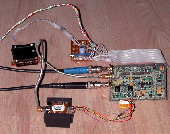
Interesting military/commercial surplus gear is common on eBay, but rarely does an item's coolness-per-dollar figure reach that of these little microwave synthesizers. Appearing (circa 2006) in several auction lots for US $19.99 each, these user-friendly modules are capable of phase-locking almost any YIG-tuned oscillator in the 2-12 GHz range. They're intended for use with the Stellex/Endwave 6755-725F and 6755-726F YTOs, also widely available on eBay, but are easily modified for use with other YTO models.
Some key features include:
- Operates from +5V and +8.5V DC supplies
- Based on popular LMX2326 2.8-GHz PLL chip with simple three-wire serial control interface
- Includes onboard divide-by-4 prescaler driven by YIG coupling loop and two MMIC gain stages
- Includes onboard TCVCXO (temperature-compensated voltage-controlled crystal oscillator) with approximately +/- 100 ppm tuning range
- Power opamps with 1A current capability can drive YIG tuning coils directly
The documentation provided by the seller was very helpful, but it omitted a couple of key specs such as the intended phase-detector comparison frequency, as well as important performance characteristics including phase noise and lockup time. Get the comparison frequency wrong, and your synthesizer may work only in "spread spectrum" mode! So, before contemplating any embedded applications for the Stellex synthesizer, it made sense to develop an experimental application that could control the synth from my Windows PC, with the goal of determining the missing specs empirically.
Several recent projects have used the LMX2326 PLL and similar chips, so I already had a good head start at programming the synthesizer. My control program, stellex.exe, along with all of the schematics and other documentation I received from the seller, may be downloaded here.
Full C++ source code, compatible with both Microsoft Visual Studio 2005 for Win32 and AVR-GCC for Atmel microcontrollers, is also included in this zipfile.
To run stellex.exe on a Windows 2000 or XP box, you will need to connect the synthesizer to a parallel port on your PC as follows:
| 20-pin connector on board | DB-25 LPT port connector | Signal |
|---|---|---|
| 12 | 4 | LATCH |
| 10 | 3 | DATA |
| 7 | 2 | CLOCK |
| 14 | 15 | LOCK_DETECT |
| 1,2,3,4,17,18 | 18-25 | GROUND |
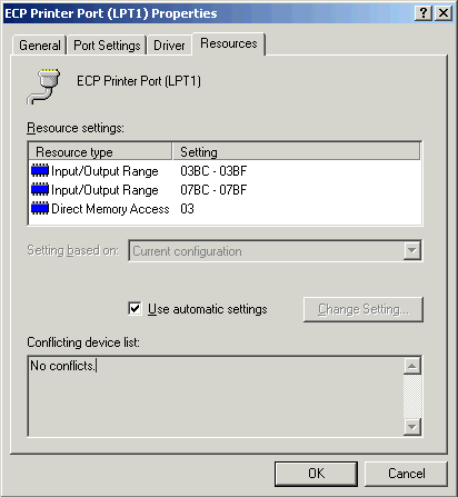
Next, you'll need to determine the base address of the parallel port. This can usually be done by inspecting the first Input/Output Range entry in the Resources tab for your parallel port in the Windows Device Manager. It will usually be 378, 278, or 3BC.
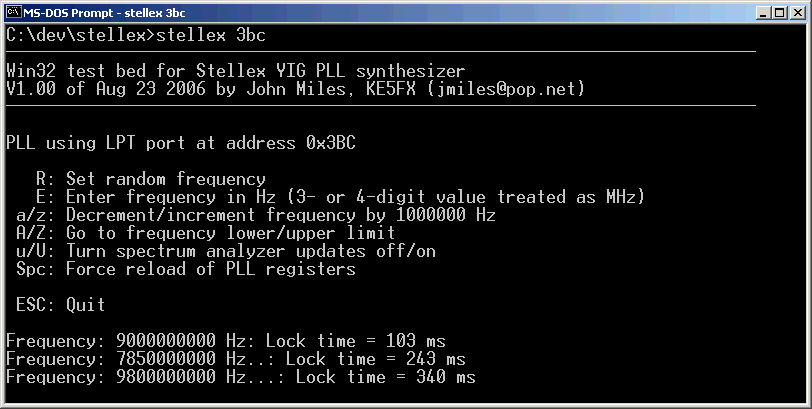
Once you know this base address, you should be able to run a command of the form stellex 3bc at a DOS prompt or as a Start->Run command from the taskbar.
 The synthesizer should lock within a few hundred milliseconds at most. If, instead, you
see a continuous line of periods (. . .), you'll need to do some troubleshooting. Search for
a few of the different ways to verify that your parallel-port base address is correct.
Try setting the port to standard mode, rather than ECP/EPP. Hang a scope on pin 2 (the first data line) to watch for
activity when stellex.exe starts up.
The synthesizer should lock within a few hundred milliseconds at most. If, instead, you
see a continuous line of periods (. . .), you'll need to do some troubleshooting. Search for
a few of the different ways to verify that your parallel-port base address is correct.
Try setting the port to standard mode, rather than ECP/EPP. Hang a scope on pin 2 (the first data line) to watch for
activity when stellex.exe starts up.
One possible source of trouble: in order to achieve reliable lockup detection, I had to remove a 1K resistor from my synthesizer board between pin 14 of the LMX2326 (Fo/Ld) and pin 14 of the 20-pin IDC header. This resistor does not appear on the schematic. Replace it with a much smaller one (100 ohms or so), or a jumper. Otherwise, the pullup resistors in your PC's parallel-port interface may be too "stiff" to allow the lock-detect line to be read.
Another problem lies in the reversal of connections to pins 19 and 20 in at least some versions of the 6942A_2 ("CODELOADER INTERFACE CABLE") diagram provided with the synthesizer. Pin 19 is the 10 MHz output sample from the TCVCXO, while pin 20 is the TCVCXO's tuning control voltage. These pins are shown correctly on the other two diagrams ("BEST_INTERFACE_SCHEMATIC2" and "GOOD_INTERFACE_SCHEMATIC1").
Other than these minor issues, the connections shown on the CODELOADER_CABLE.pdf interface cable schematic are all that's necessary to run stellex.exe.
Update, July 10, 2010: I've revised the stellex.exe control program to support a wider range of oscillators. Three new optional command-line parameters allow you to specify the minimum, maximum, and initial tuning frequencies in MHz. For example,
will program the Stellex synthesizer at LPT port address 3BC for tuning between 9 and 11 GHz. The default frequency at program startup will be 10 GHz.stellex 3bc 9000 11000 10000
As always, you can run stellex.exe with no command-line parameters for a list of options supported by the current version.
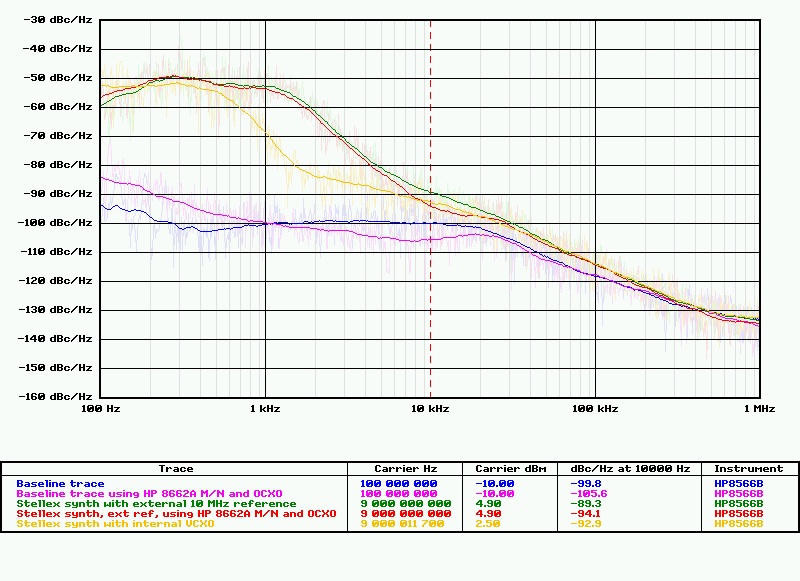
It didn't take long to determine that the synthesizer's intended comparison frequency appears to be 250 kHz. To begin with, the comparison frequency has to be an integer factor of the 10 MHz clock frequency, because the LMX2326's reference divider accepts only integer R values. If we limit ourselves to Fcomp options that result in whole-number output frequencies when multiplied by arbitrary integer N values, a relatively-small set of possibilities emerge. These, in turn, are easy to compare with a spectrum analyzer:
- 5 MHz: Loop unstable
- 1 MHz: Loop locks, but with large 'ears' a few kHz from the carrier
- 500 kHz: Relatively-stable, less peaking
- 250 kHz: Seems optimal; stable and consistent behavior during frequency transitions
- 200 kHz: Also relatively stable
- 100 kHz: Very slow locking/stabilization times observed
- 50 kHz: Loop unstable
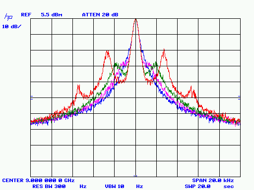
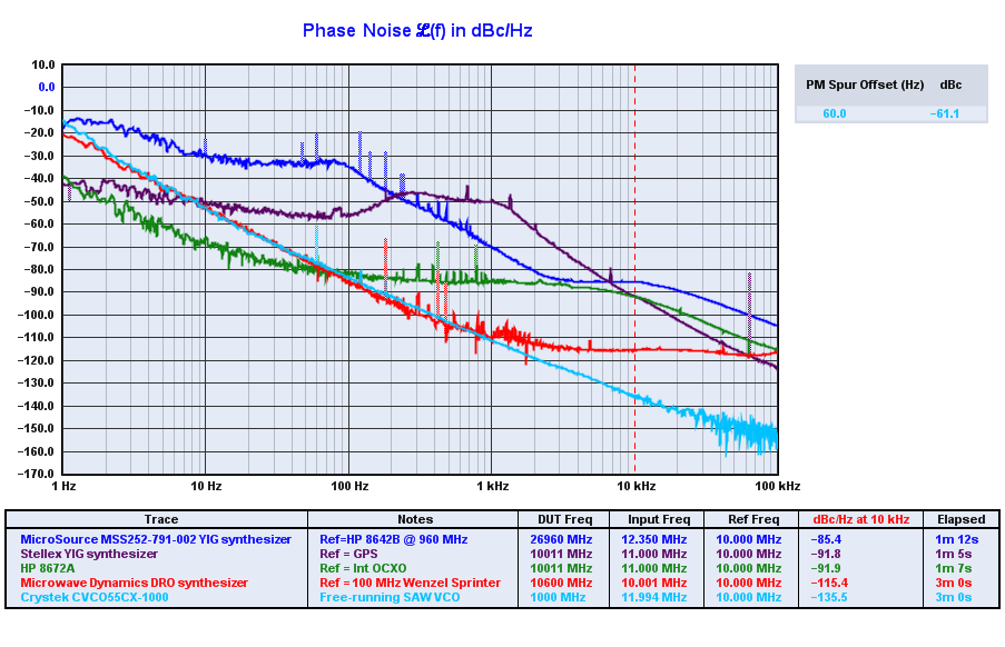
The phase-noise measurements below were taken
with the 250 kHz Fcomp value.
 It proved difficult to stabilize the TCVCXO sufficiently during the
90-second phase noise measurement sweep. The yellow trace reflects the best of several attempts.
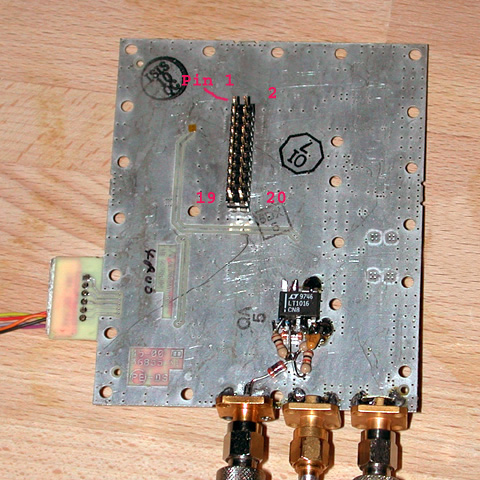
Eventually, I gave up and removed the TCVCXO from my board, installing a third SMA jack and
an LT1016 high-speed comparator in its place to allow the board to operate from an
external 10-MHz clock source. This modification, visible at right, is a worthwhile one for
most applications... unless you plan to stabilize the onboard TCVCXO with its own PLL!
It proved difficult to stabilize the TCVCXO sufficiently during the
90-second phase noise measurement sweep. The yellow trace reflects the best of several attempts.
Eventually, I gave up and removed the TCVCXO from my board, installing a third SMA jack and
an LT1016 high-speed comparator in its place to allow the board to operate from an
external 10-MHz clock source. This modification, visible at right, is a worthwhile one for
most applications... unless you plan to stabilize the onboard TCVCXO with its own PLL!
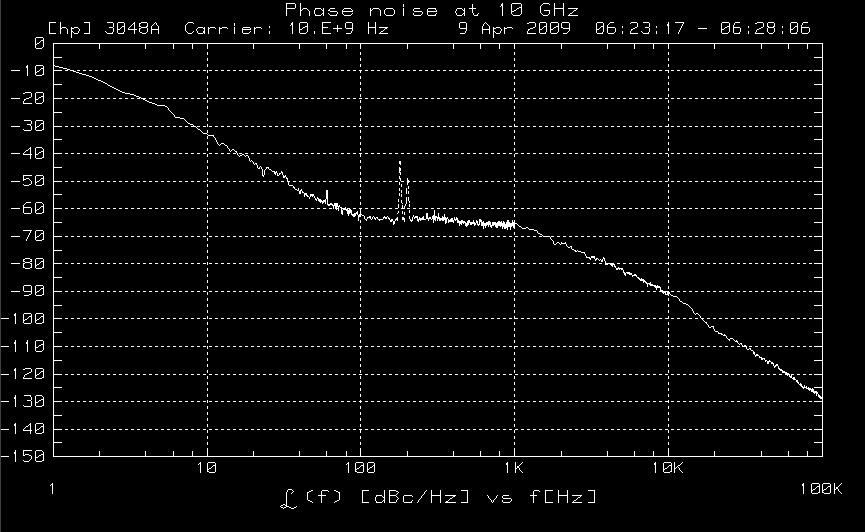
Once the board was operating from a stable 10 MHz reference, another problem with the phase-noise measurement process became apparent: the synthesizer was too clean for the HP 8566B spectrum analyzer to measure accurately at offsets beyond about 5 kHz from the carrier. Note the increasing convergence of the blue analyzer-baseline trace and the green measurement trace in the graph above. This situation is worse than it looks: a proper noise baseline trace, if taken at the measurement frequency of 9 GHz where harmonic mixing is used, would be at least 6 dB higher than these 100-MHz traces.
A partial solution to this measurement difficulty can be reached by opening up the HP 8566B and replacing its own YIG synthesizer reference with a cleaner version obtained from an HP 8662A signal generator.
Briefly, when the analyzer is tuned to center frequencies near 9 GHz, an internal "M/N" reference signal is generated at approximately 189.565 MHz. The M/N signal is used as a basis for phase-locking the analyzer's local oscillator, so any improvement in M/N spectral purity will improve the analyzer's baseline noise performance. (See HP Application Note 283-3, chapter 11, for an overview of this technique as it applies to the physically-similar HP 8672A microwave signal generator.)
The purple baseline trace reflects this improvement, as does the red measurement trace...
not a dramatic difference, but enough to reveal that the Stellex synthesizer is performing a few
dB better than initially observed. The peaking characteristics in the analyzer's baseline trace, even the improved one,
are still clearly visible in the measurement trace at offsets between 10 and 30 kHz.
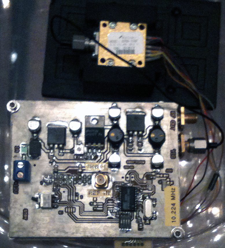
Important: If you add an external
clock input to your board, keep both its signal path and ground return away from the PLL chip's RF input circuitry, including the YIG input jacks and prescaler/buffer MMICs. You may have trouble getting the synthesizer to lock if there's any
clock-induced ground bounce or crosstalk. Avoid doing what I did in this photo, where the ground return from the 10 MHz clock
ran near the RF input traces. Ideally, any clock-input hardware and wiring should be added near the opposite edge of the board, as
seen in my later prototypes below.
April 9, 2009
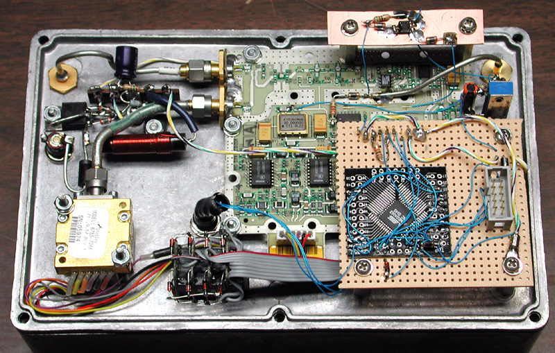
Here's a compact microcontroller implementation of a YIG synthesizer built with the Stellex board. This version was constructed around an Atmel ATTiny2313. Despite the chip's stripped-down specifications (2KB code space, 128 bytes SRAM), it was still possible to write the firmware in C/C++ using the free WinAVR GCC package. You can download this code here.
Even if you're using a different microcontroller (PIC, etc.) in your project, I'd recommend basing your firmware development on the stellavr.cpp module in this zipfile. It's much easier to read, debug, and customize than the Windows version mentioned above.
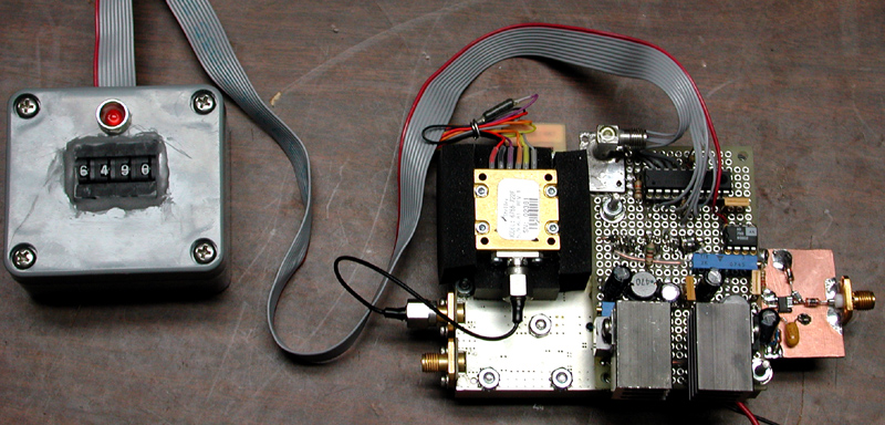
Another Atmel implementation used similar firmware with the
ATmega163. I used the ATmega163 here because it was handy; this version of
the synthesizer could also have used an ATTiny2313 or similar low-end part.
Below, an interior view reveals the same BCD thumbwheel switch and MC100EL16 input-clock conditioner that the earlier project used, along with
the necessary regulators to allow operation from a single +12V supply. The clock shaper circuit
is identical to the input stage in an earlier comb generator project.
A toggle switch allows selection of an external 10 MHz source or the board's own 10 MHz TCXO. Again, be careful to keep the LMX2326's clock-reference and RF paths separate.
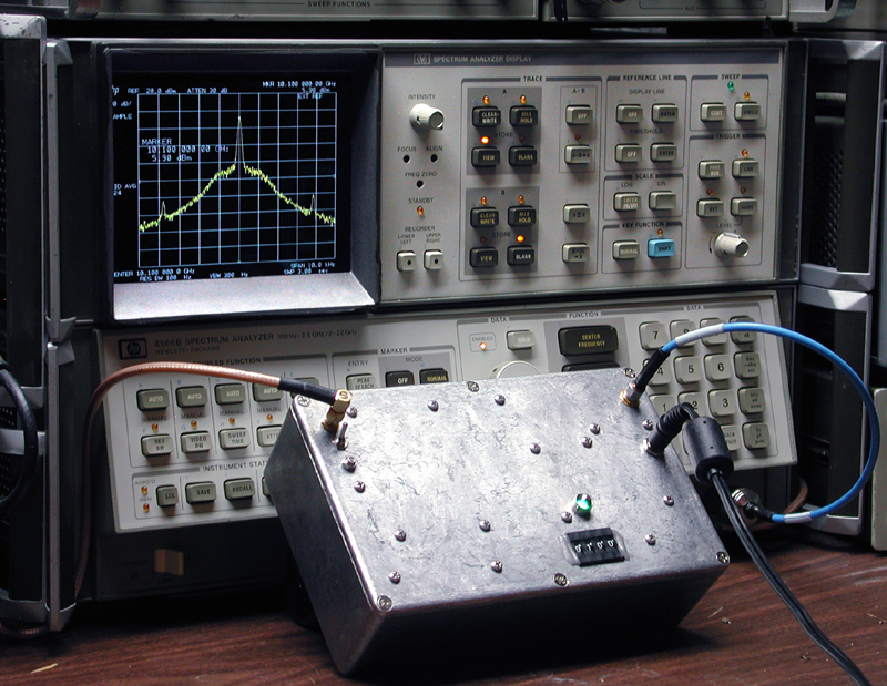
In-band phase noise is about -65 dBc/Hz, or approximately 15 dB better than composite noise (AM+PM) measurements made
via spectrum analysis, either with PN.EXE or as seen in the 8566B photo
above. I'm not sure why the difference is so large... some AM noise may be showing up on the spectrum analyzer and not on
the 3048A, but I'm not sure where it would come from. More investigation is needed (see March 13, 2013 update below).
The clock source for this measurement was the 10 MHz output from a Trimble Thunderbolt.
Technical Correspondence and Further Development
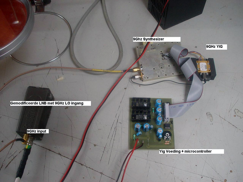
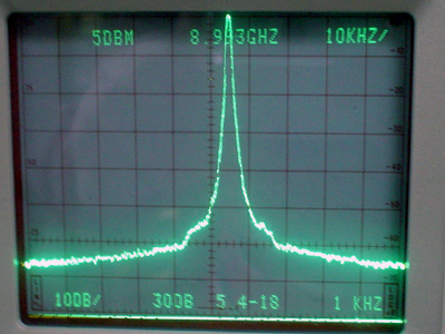
April 9, 2009 Evert Verduin sends along some photos of his 10 GHz synthesizer based on the PIC 12F629:
June 24, 2010 Bruce Ekert, VK2EM adds a couple of observations regarding frequency coverage and programming:
You were right (in private email) about the unit not oscillating up to 10GHz and higher. The actual + voltage at the YIG was not high enough. There was about 1.8V dropped through the controller, which meant that the YIG would never reach the same frequency as when a direct regulated voltage was applied to it.Thanks to Bruce (and Andy) for these useful tips. If you leave your YTO in the block of foam used for microphonic protection, make sure it doesn't overheat!Regarding (PIC programming), I found on the net, on the website of Andy Talbot, G4JNT, some of the info that I needed. Andy and his radio club have done extensive work with beacons, repeaters, etc, and they have programmed LM2326 PLLs for these uses. I wrote to Andy, and he was kind enough to send me 2 links which he had overlooked putting on his site, which deal directly with programming 12F675 PICs to control LM2326s. Here are the links...
http://www.g4jnt.com/BridgeWave_Synth.pdf
http://www.g4jnt.com/bridgewave.zipYou may find something interesting there, courtesy of Andy.
July 10, 2010 Jeffrey Pawlan, WA6KBL has compiled some excellent notes on improvements for the Stellex synthesizer board, especially in regard to increasing its power output. (Text and photos in this section copyright 2010 by Jeffrey Pawlan; all rights reserved.)
These surplus MiniYIG synthesizer boards have provided hams and experimenters with an easily programmable RF source in the range of 7.5GHz to 10.5GHz, depending on the specific model YTO. Data and code samples on the KE5FX page have been very helpful, allowing us to get up and running quickly. However, I immediately noticed a large discrepancy between the output power of the YTO alone and the power coming out of the second port of the synthesizer board. The YTO produces at least +14 dBm, yet the power available from the synthesizer board, measured on several boards, is much lower. Between +5.5 dBm and +7 dBm is typical at 9 GHz and below, but the level drops off to -1 dBm at 10 GHz and higher. Neither is sufficient to properly drive the LO port of a passive mixer.Thanks to Jeffrey for the detailed account of his work with the board!Although one could design and build a simple amplifier to increase this power level, it would waste power, add noise, and increase overall complexity. Being a microwave engineer, I wanted to see why so much power was being lost and what could be done about it.
By design, the output of the YTO is passed through a directional coupler which samples some of the RF for phase locking. The directional coupler is followed by two resistive pads and two gain stages before reaching the divide-by-four prescalar. On the connector side, the coupler has either a pi pad or a resistor at each of its two ports. We do not know the design specifications of the system into which this synthesizer was connected, so we do not know why the designer wanted to deliberately attenuate the signal. For our needs, we do not want to attenuate the power out of the YIG any more than necessary to extracy a small sample for phase locking. After a few easy modifications, I was able to obtain between +11.5 dBm and +13.5 dBm from the board.


Above, you will see the two attenuators at each end of the directional coupler's main arm. The second photo shows a variant of the board where there is only one attenuator and the other end of the coupler has a series resistor. Testing the synthesizer board with an external signal of known level, I found that there is plenty of sensitivity without the need to remove the two resistive pads preceding the first amplifier. After changing the directional coupler to a single-port signal sampler, I was able to use a commercial directional coupler to provide the small signal needed by the synthesizer for phase locking.
As shown in the block diagram of the modified system at left, you will connect the external directional coupler's input port directly to the YIG oscillator. I suggest using a double male SMA adapter. The coupler's loss must be 10 dB, preferably covering the entire band of interest. The ideal parts are those rated for 8 GHz - 12 GHz. You may be able to use couplers specified for an adjacent band, but do not try anything lower than 7 GHz or higher than 14 GHz or the resulting coupling factor will be too far off.
The output of this external directional coupler becomes the synthesized signal output. If your YTO and synthesizer are working properly, you will obtain between +11 dBm and +13.5 dBm, depending on the frequency. The coupled port of this external directional couple will be connected to the single port on the modified synthesizer board.


When modifying the synthesizer board, the two SMA connectors are carefully unsoldered first to avoid damage to the board. Do this by supporting the board with the metal housing so the connector flanges are not touching anything. The two attenuator pads are then removed. This will require the use of two soldering irons simultaneously, if you don't have a tweezer-style desoldering tip. Use a standard wattage iron for the ground end, or you will not have enough heat. A microfine iron can be used at the signal end of the pad.
Clean the solder off of the pcb traces including the ground area. This is best done with solder wick and rosin flux. Orient the board so that the connector cutouts are at bottom right. This bottom-right corner will no longer have a connector; you will install a termination resistor in its place. The resistor goes between the end of the bottom of the directional coupler main arm and the ground pad just below it, near the R1 label. A 51-ohm 0603 chip resistor will work well. Place the resistor so that one end pad is close to the ground via hole to minimize seies inductance, and solder this end first, followed by the other end pad of the resistor at the 50 ohm trace of the onboard directional coupler. Closeups of this termination-resistor installation can be seen in the photos above.
The other end of the onboard directional coupler must be bridged directly to the pcb trace where the SMA center pin is connected. Since there is a break between the coupler trace and the connector trace, you will need to cut a very small piece of copper foil, tin it with solder, and solder it across the gap, as shown at right.
You are now ready to re-solder the single SMA connector to the board at the upper slot on the right-hand side. You may need help holding the board while soldering. You will need to put the board on top of the metal housing so that the connector flange does not touch your bench. Make sure that the line in the metalized gasket lines up with the edge of the board. While the board is firmly held in place, push the connector against the cutout slot so that the back of the connector lightly touches the side of the PCB. This minimizes the length of the bare centerpin before it reaches the top of the 50 ohm pcb trace. Solder it to the trace with only a small amount of solder.

Assemble the connector to the side of the housing with the two screws and washers. This will prevent the connector from ripping the trace on the board. You will also need to either tape the board to the housing or fasten it with screws through the housing. The completed assembly with the YIG and external directional coupler is shown at left.
Additional Notes
I've found that the labels on the YIG oscillators are frequently incorrect, and their actual tuning range is different than indicated. Using the latest version of stellex.exe you can find the minimum and the maximum lockable frequencies.


Finally, as noted by KE5FX, to enable lock detection via the stellex.exe control program you will need to solder a lower-value shunt resistor across the 1000 ohm resistor R24, as seen in the photos above. This resistor is located below the black plastic dual inline header connector. I suggest a 100 ohm 0603 chip resistor.


October 25, 2010 Among many interesting microwave projects by Goran, AD6IW is this outboard controller mounted atop the Stellex board's aluminum casting.
December 6, 2010 Here's one way to drive the Stellex board's LMX2326 PLL -- just use an inexpensive USnooBie controller board! This board is similar in some ways to the popular Arduino platform, in that it uses an Atmel AVR-series microcontroller and can be programmed over USB with no need for additional hardware. However, it's much simpler than an Arduino and much less expensive as a result. As of December 2010, the USNooBie can be ordered as a kit directly from the Chinese distributor Seeed Studio for only US $16.
 In this photo at right, I've modified one of the synthesizers shown earlier on this page by replacing its original ATmega163 chip with a USnooBie. As a result, I can reprogram the board over USB, instead of dragging my Atmel STK-500 programmer out of the closet.
The source code and precompiled .hex file may be downloaded here. A makefile is provided to recompile the .cpp module if desired, or you can just run p.bat to upload the .hex file after putting the USnooBie in its bootloader mode as demonstrated in the video on the USnooBie page.
To get a copy of the required avrdude.exe programmer utility, you'll need to install either the WinAVR toolkit distribution if you're working under Windows, or the appropriate version of avr-gcc and its associated tools for other platforms. (You could also use the more up-to-date MHV AVR Tools distribution or Atmel's own AVR Studio toolchain, but I'm still using WinAVR as of this writing.)
The connections between the Stellex board's 0.1" header and the USnooBie are listed in the table below.
| Synthesizer pin | USnooBie pin | Signal |
|---|---|---|
| 10 | B1 | DATA |
| 7 | B2 | CLOCK |
| 12 | 3 | LATCH |
| 14 | B4 | LOCK_DETECT |
| 1,2,3,4,17,18 | GND | GROUND |
| 5,6 | V+ | +5 VDC |
In addition to the required connections to the Stellex board, the firmware assumes that a two-color red/green LED is connected to the C4 and C5 pins for use as a lock indicator. The LED's common anode is tied to the +5V pin on the USnooBie board, and appropriate resistors (470 ohms or so) are used in the two cathode leads to limit the current.
The firmware expects the frequency in MHz to be entered with a 4-digit BCD thumbwheel switch. Each of the four switch digits has a common contact and four other contacts marked 1, 2, 4, and 8. The switch represents a given digit from 0-10 by closing a circuit between its common contact and the appropriate combination of binary place values that add up to the digit in question.
You'll need to connect the individual digits' common lines to pins D0 (LSD, "ones" place) through D3 (MSD, "thousands" place). The binary place-value contacts at all four switches are connected in parallel with 1N914 or similar steering diodes and tied to pins C0 ('1'), C1 ('2'), C2 ('4'), and C3 ('8'). Click on the photo above for a closer look at this arrangement.
In operation, the microcontroller "addresses" each switch in turn by grounding that switch's common pin at D0-D3, and then reads the switch's value by polling the rudimentary four-bit data bus created by wire-OR'ing the four switches' binary place-value terminals together with the steering diodes. This scheme allows values from 0000-9999 to be read with only eight wires. (Frequencies above 10 GHz are entered with the '1' digit omitted; e.g., 0050 would be 10050 MHz.)
Finally, when using a USnooBie or similar board to drive the synthesizer, you can (and should) omit the controller board's own power-distribution components. The Atmel chip should receive +5V only from the supply that drives the rest of the synthesizer hardware, even when it's being programmed over USB. You could use Schottky diodes to power the microcontroller from either USB or the synthesizer supply, but this can cause the MCU to send power to the PLL chip through its output pins, causing flaky behavior (at best). In the USnooBie's case, you should omit F1, IC2, JP4, and the jumper that would ordinarily be used at D3.
Note: It appears that the first few USnooBie boards have shipped with the wrong bootloader code. If you have trouble getting Plug-and-Play to recognize the board properly and install its V-USB drivers, and you don't have the necessary hardware programmer to reflash the ATmega328P with the necessary atmega328p_2k_12000000.hex file from the USnooBie Downloads page, you'll need to contact frank (at) circleofcurrent (dotcom) for assistance.
March 11, 2013 An experimental PN measurement system using a pair of uncorrelated downconverters yields another view of the Stellex synthesizer's close-in noise, placing it in context with several other microwave sources:
Unlike any of the earlier plots on this page, the trace above corresponding to the Stellex measurement is not affected by reference or instrument noise. It actually agrees more closely with the earlier results from the HP 8566B spectrum analyzer than with those from the more-elaborate HP 3048A system.
It's possible that the excessive close-in noise reported by the
HP 3048A is caused by violation of the small-angle criterion associated with L(f) measurements (see page 7 of Decker & Semple), but why does the inband noise between 100 Hz - 1 kHz appear to be underestimated by the 3048A? The conclusion from the April 2009 measurement still stands: "More investigation is needed."
June 23, 2015 Dave Donley, KK6UQN writes:
Thank you for your excellent Stellex notes page and software bundle. Using the information and software I was able to quickly bring up a USB-configured Stellex programming MCU. I am using the synth to drive a mixer for a 10 GHz radio. I put up a page describing what I did here: http://www.mrdonley.com/10-ghz-almost-thereDave also plans to release his port of the Stellex software to the LPC11U14 MCU for the NXP LPCXpresso toolchain, so check that page if you're interested in doing any embedded work on that platform.
July 22, 2015 Luis Cupido, CT1DMK has posted The Ultimate Plug and Play Stellex Mini-YIG Synthesizer Controller. This project is unique in that it allows you to configure an Arduino Nano 3.0 (or compatible) board to support the Stellex synthesizer without having to install the Arduino IDE or other build tools.