Equinox: A Remotely-Controlled DC-1 GHz
Communications Receiver and Trunk-Tracking Scanner

The Equinox client, server, utilities, and firmware may be downloaded here (2 MB). This package includes binaries for Win32 and Atmel, as well as full source code.
You can also download a brief PowerPoint presentation on Equinox at left. This presentation was delivered at a 2005 meeting of the dorkbot-seattle group.
 Architecturally, the Equinox main receiver is a quad-conversion superheterodyne with
intermediate frequencies at 1080.7 MHz, 110.7 MHz, 10.7 MHz, and 455 kHz. A dedicated, fully-autonomous
800-MHz data receiver monitors the local Motorola SmartNet radio system control channel to
facilitate real-time trunk tracking.
Architecturally, the Equinox main receiver is a quad-conversion superheterodyne with
intermediate frequencies at 1080.7 MHz, 110.7 MHz, 10.7 MHz, and 455 kHz. A dedicated, fully-autonomous
800-MHz data receiver monitors the local Motorola SmartNet radio system control channel to
facilitate real-time trunk tracking.Each receiver has its own Atmel ATMega128 microcontroller. These, in turn, are controlled by a Via EPIA Mini-ITX motherboard that acts as a TCP/IP server for command and audio streaming, interfacing the receiver hardware to the outside world.
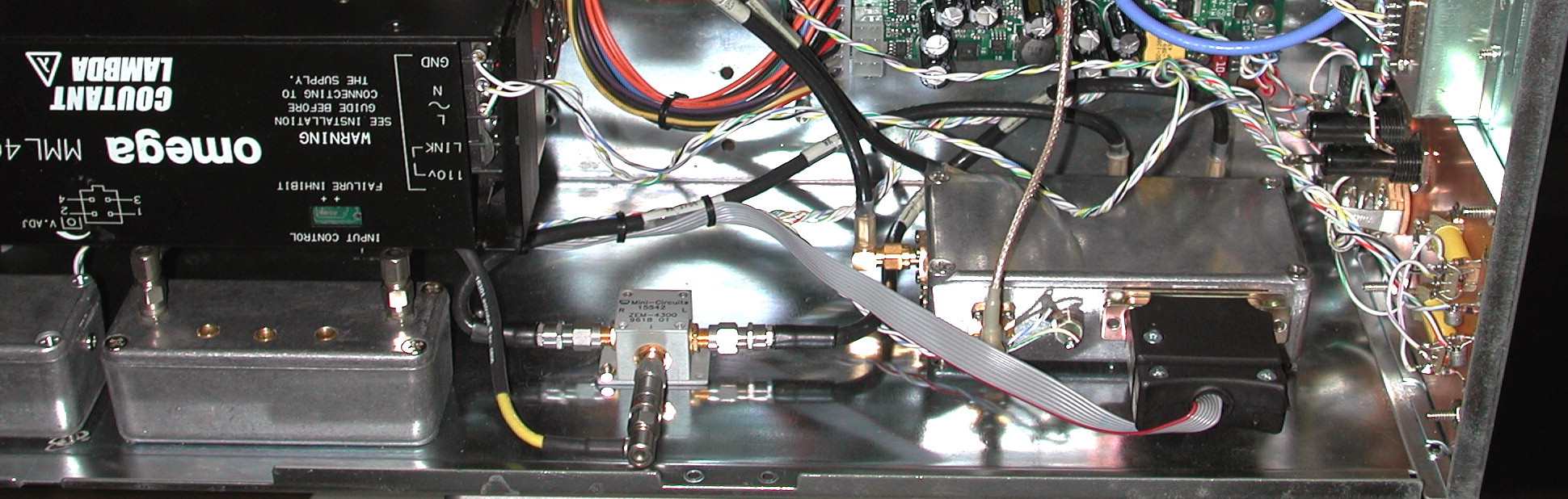
Independent power supplies for the receiver and Mini-ITX motherboard, as well as extensive RF shielding and compartmentalization, help keep interference to a minimum. A Lambda MML400 switching supply runs the receiver hardware, while the server motherboard operates from an M1-ATX power module from Mini-box.com.
At present, the main receiver has no front-end preselection, only a single low-pass filter for the frequencies below 30 MHz and a five-section cavity filter for the critical 800 MHz public service band. This "feature" makes Equinox resemble a spectrum analyzer more than a conventional receiver!
IMD can certainly be a problem, especially on the aircraft and Amateur bands surrounding the local FM and VHF TV powerhouse stations, but in general it's surprising how well the receiver works with no front-end filtering.
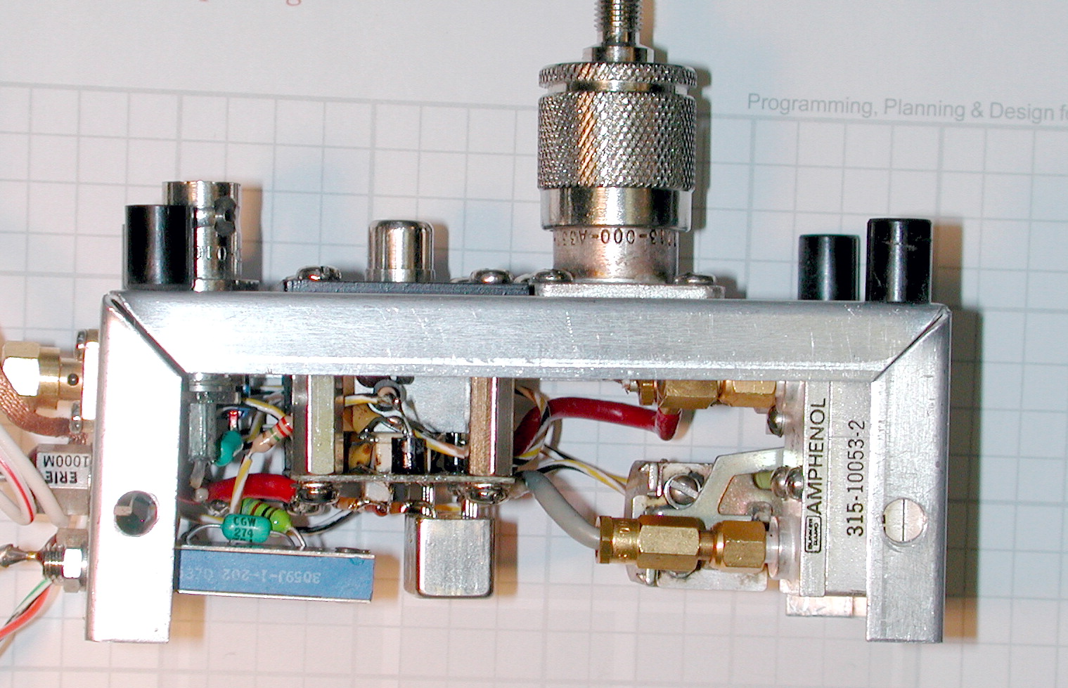
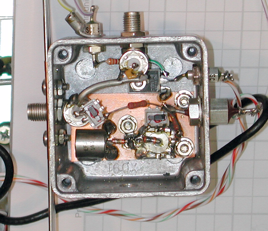
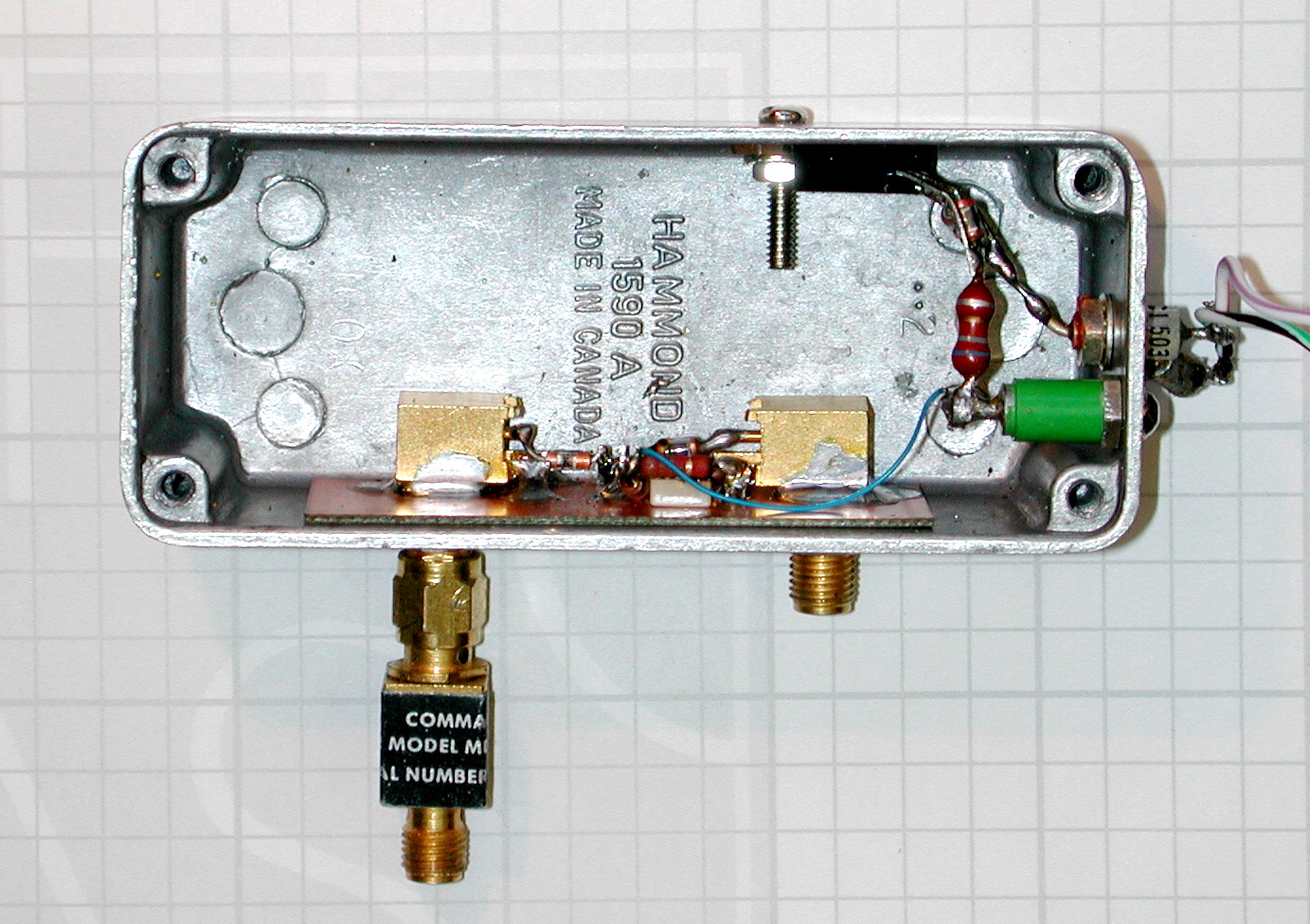
Shown here is the main antenna input assembly. Three inputs are provided: an insulated RCA jack is followed by a built-in AMRAD LF/HF preamp for a high-impedance HF antenna; a BNC jack provides a 50-ohm connection for HF; and an N connector handles the spectrum from 30 MHz-1 GHz. RF preamplification on the VHF/UHF bands is provided by a Mini-Circuits GALI-4 MMIC.
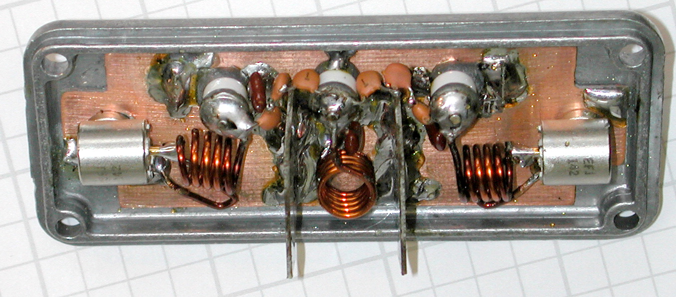
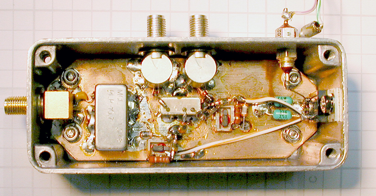
 The next two photos show the surplus 800 MHz cavity filter (retuned to 850-870 MHz) and dedicated
SMA connector/preamp assembly for 800 MHz support. A bias tee provides 12 volts DC at the SMA
jack to power an antenna-mounted MMIC preamplifier.
The next two photos show the surplus 800 MHz cavity filter (retuned to 850-870 MHz) and dedicated
SMA connector/preamp assembly for 800 MHz support. A bias tee provides 12 volts DC at the SMA
jack to power an antenna-mounted MMIC preamplifier.
The dedicated 800 MHz front end not only dodges the IMD bullet mentioned above, but also makes it easy to use a directional antenna
for reduced multipath interference. While Equinox won't win any awards for HF/VHF
dynamic range, its performance in 800 MHz
trunk-tracking applications is second to nothing on the market.
An Analog Devices ADF4112 PLL chip drives a Mini-Circuits ROS-2150VW VCO, with its reference supplied by a high-resolution AD9852 DDS. Loop bandwidth is in the 2 kHz range, kept consistent across the band by varying the ADF4112's charge pump gain in software.
Phase noise is approximately
-93 dBc/Hz at 10 kHz from the carrier, competitive with exotic commercial/military receivers such as
the Watkins-Johnson 8628A-4.
As with many of the Equinox modules, the first LO's digital control interface is compatible with both the ATMega128 port used by the receiver controller and a conventional PC parallel port, an invaluable troubleshooting feature. It's easy to pull modules out of the receiver and power them up on the bench for testing, using Win32 console apps that run the same C++ code as the receiver firmware.
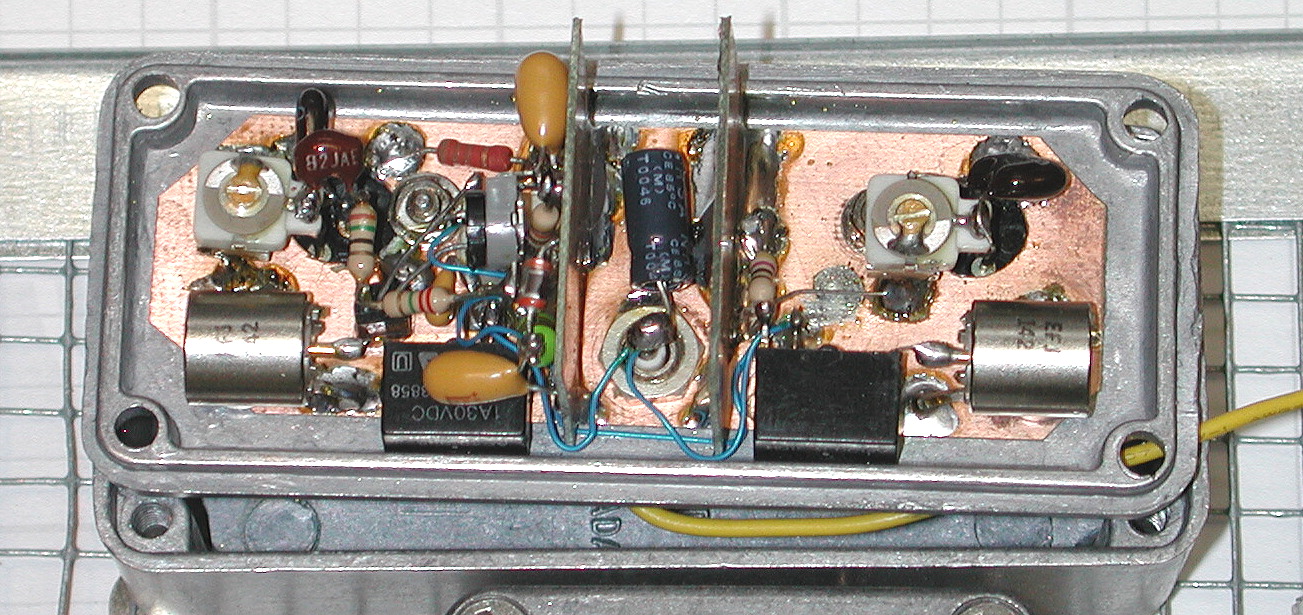
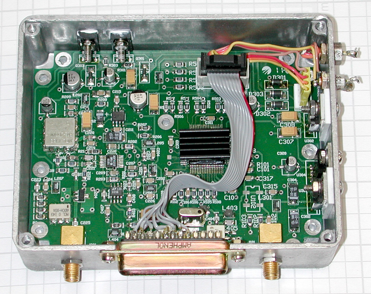
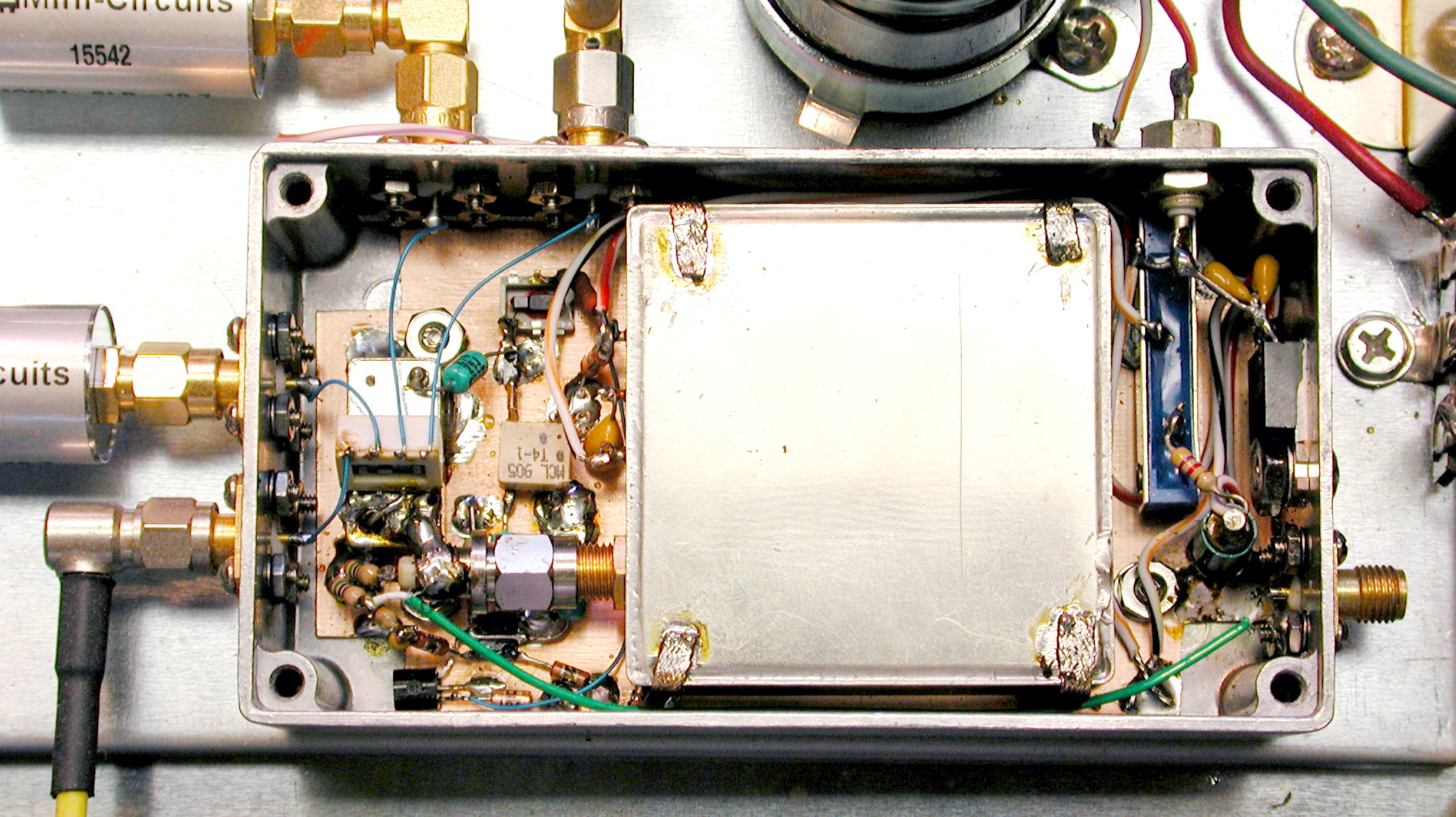
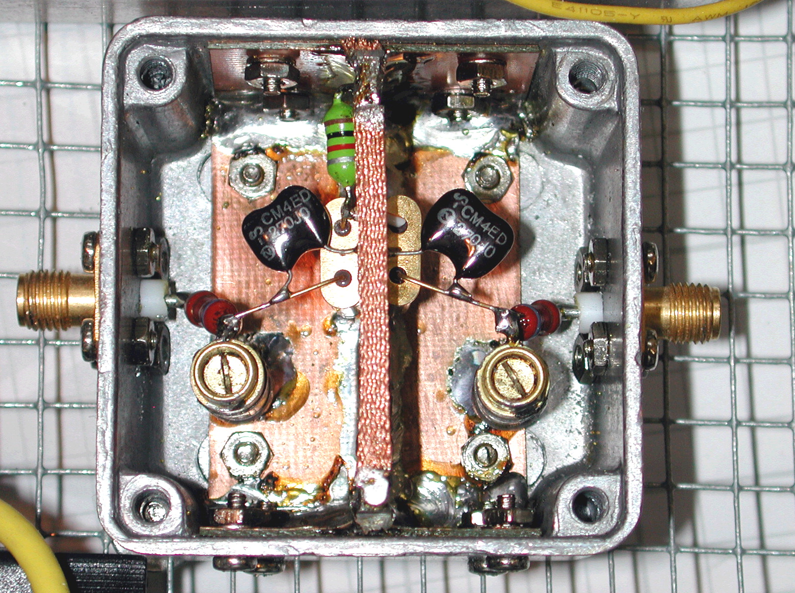
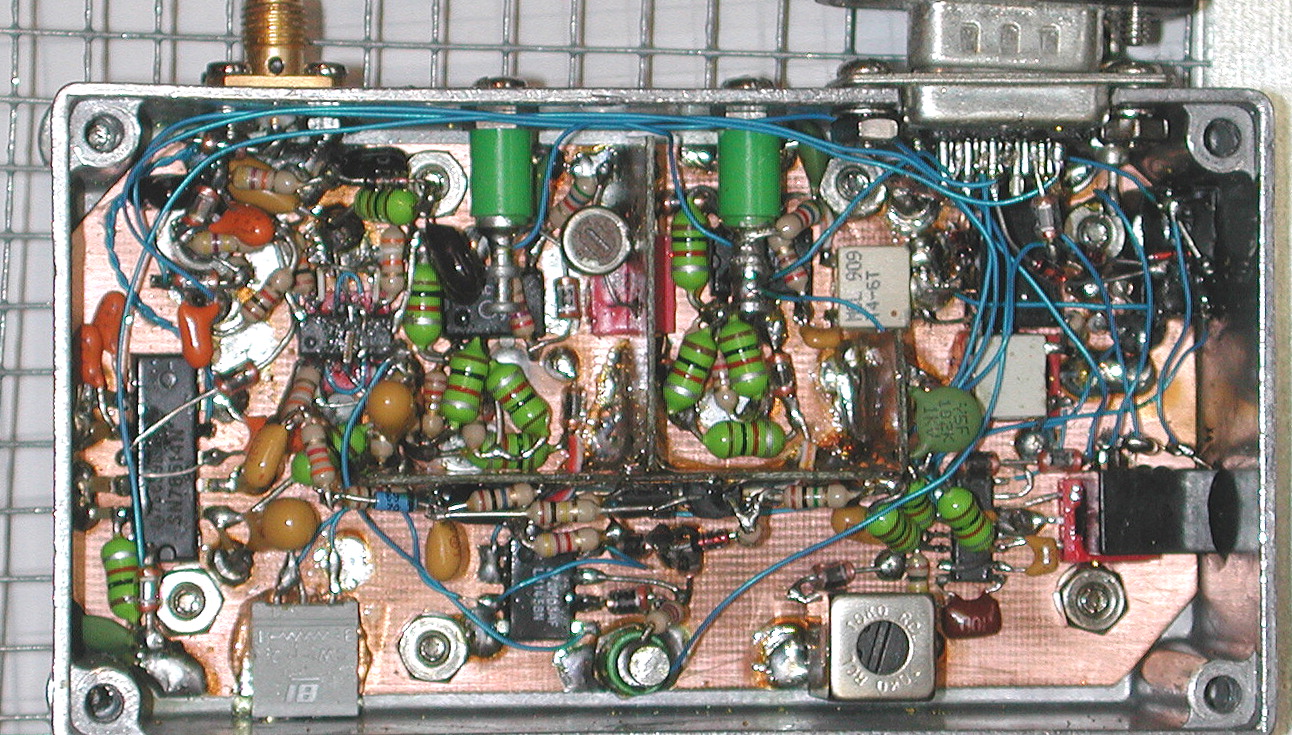
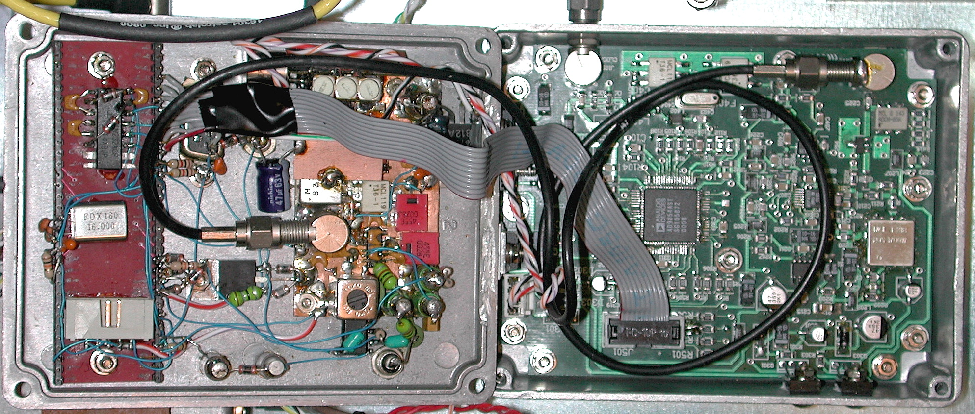 A second KE5FX/VK6BRO synthesizer lies at the heart of the self-contained 800 MHz data receiver
used to monitor the SmartNet control channel. It's overkill in this case, since this receiver
"lives" on a single frequency, normally 868.175 MHz plus or minus the 455 kHz IF. The ATMega128
controller (visible at far left) switches sidebands if it appears that image interference is
causing packet-decoding problems.
A second KE5FX/VK6BRO synthesizer lies at the heart of the self-contained 800 MHz data receiver
used to monitor the SmartNet control channel. It's overkill in this case, since this receiver
"lives" on a single frequency, normally 868.175 MHz plus or minus the 455 kHz IF. The ATMega128
controller (visible at far left) switches sidebands if it appears that image interference is
causing packet-decoding problems.
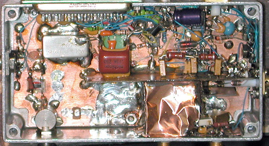
Besides the hybrid synthesizer, the data radio's front end comprises a three-section Toko filter followed by a GALI-4 preamp and TFM-150 double-balanced mixer. A 36:1 transformer steps up the impedance at the mixer output to drive a Philips SA604AD FM IF subsystem IC, which is equipped with two ceramic filters and a quadrature-tuned discriminator. The SA604AD's FM-demodulated output is followed by an opamp to condition the signal on its way to the ATMega128's input capture pin.
For its part, the ATMega128 serves as a 3600-baud software modem using code derived from the popular Trunker trunked-radio decoder package. This makes for a record-breaking level of functionality in a single Hammond 1590BB box... an 800 MHz RF signal comes in on one side, and a fully-decoded stream of talkgroup/frequency assignments comes out the other! Apart from its antenna and RS-232 connections, the data receiver module needs only +15 VDC and a 10 MHz reference.
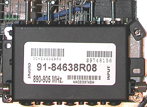
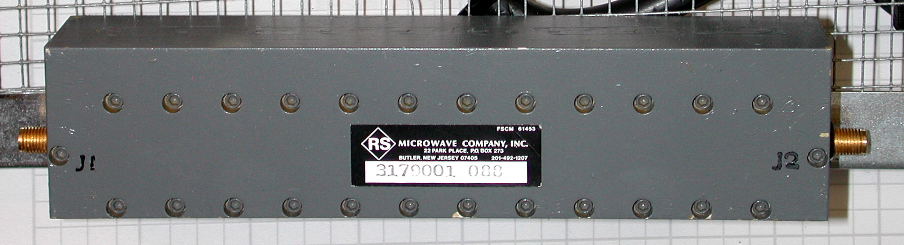
 The main receiver's post-mixer amplifier and 12-section Rohde & Schwarz IF filter are shown here.
 A 6-dB attenuator provides
a broadband termination for the first mixer, a Mini-Circuits ZEM-4300MH with
its RF and IF ports swapped. LO injection at the first mixer is approximately +13 dBm. Losses in the attenuator and filter are overcome by a GALI-4
MMIC.
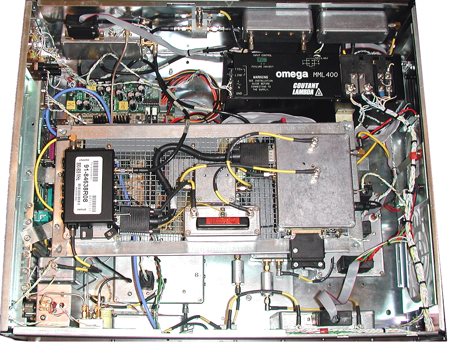
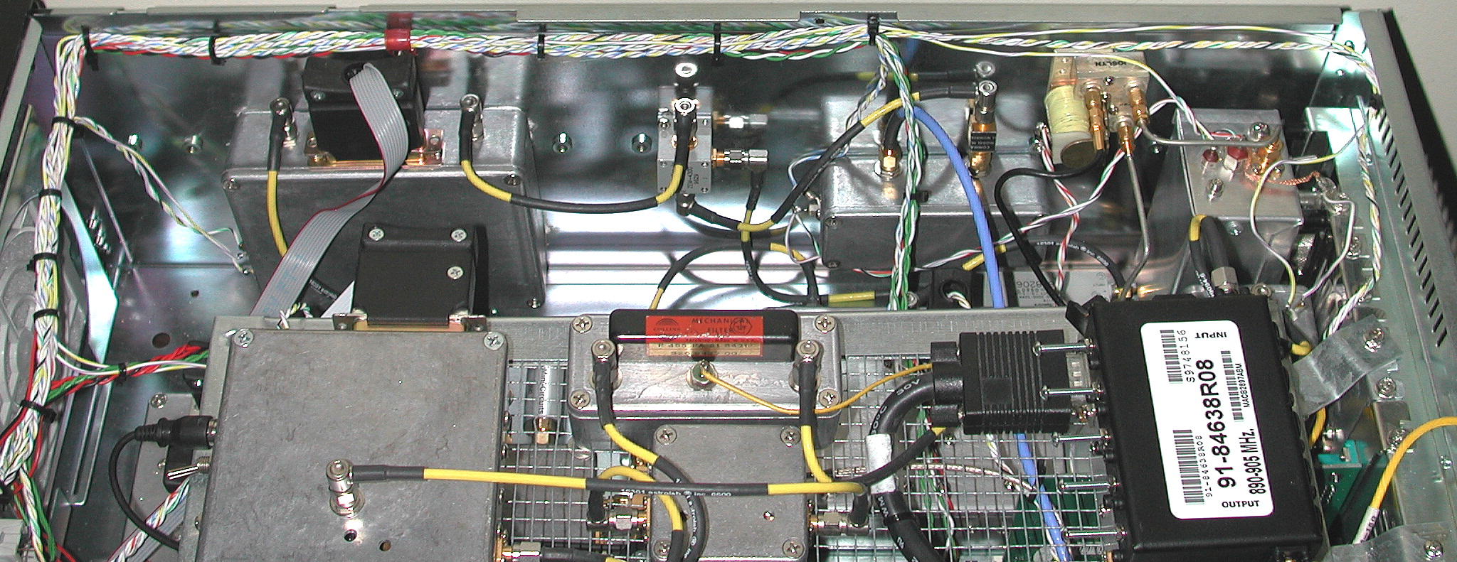
Various front-end components are visible on the wall of the receiver chassis at upper-right,
including the first LO module, first mixer, post-mixer amplifier, and the coax relay used to
switch the 800 MHz filter/antenna coupling assembly into the RF signal path. Almost obscured
beneath the IF amplifier module is the 10-dB directional coupler used to feed the 800 MHz data receiver's antenna port.
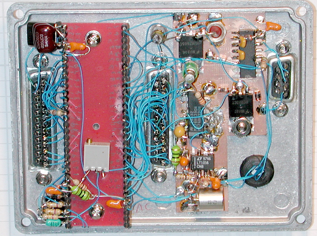
 Another interesting exercise in homebrew miniaturization is the second IF amplifier / second LO / BFO module, shown at left.
The receiver's second IF amplifier, a GALI-4 MMIC, provides about 14 dB of gain between the two
gold-plated SMA jacks on the lower edge of the Hammond enclosure. It's connected between the 110.7 MHz filter and the third
converter assemblies (below).
Another interesting exercise in homebrew miniaturization is the second IF amplifier / second LO / BFO module, shown at left.
The receiver's second IF amplifier, a GALI-4 MMIC, provides about 14 dB of gain between the two
gold-plated SMA jacks on the lower edge of the Hammond enclosure. It's connected between the 110.7 MHz filter and the third
converter assemblies (below).
The GALI-4 can deliver a similar amount of gain at the 1080.7-MHz first IF, but given the receiver's 100 MHz-wide first IF bandwidth, the amplifier's original placement between the R&S filter and the second mixer's RF input was found to be a major cause of IMD. Currently, the only gain stage between the first and second mixers is the post-mixer amplifier, described above. Examination of the photo reveals signs of extensive rework for stability, signal isolation, and gain distribution!
The second local oscillator resides above and to the left of the IF amplifier, employing an ADF4112 PLL chip to lock an ROS-1000PV VCO at a fixed frequency of 970 MHz. Amplified by another GALI-4, the output signal level at the nickel-plated SMA jack at left is approximately +13 dBm.
Again, because the R&S IF filter is 100 MHz wide at its 6-dB points, it's easy to nudge the first IF and second LO frequencies out of the way should the receiver ever be tuned near 970 MHz. This is one of two spur-avoidance tactics implemented by the firmware, the other being on-the-fly reconfiguration of the DDS clock multiplier in the first LO.
Also included in this assembly is an AD9850 DDS that serves as a 455-kHz beat frequency oscillator for SSB and CW reception. Its 0-dBm output is routed from the SMA jack at right to the product detector in the demodulator assembly. The AD9850 and ADF4112 share the 10-MHz reference input at top, next to the DC power feedthrough and DB-25 digital control connector.
 Visible on the chassis wall at right, a second ZEM-4300MH downconverts the 1080.7-MHz first IF to the 110.7-MHz
second IF, followed by a three-section LC filter originally designed by Wes Hayward, W7ZOI for his
homebrew spectrum analyzer project (see article parts
one
and
two
). A 3 dB attenuator at the mixer output helps terminate the image signal for improved IMD
performance.
Visible on the chassis wall at right, a second ZEM-4300MH downconverts the 1080.7-MHz first IF to the 110.7-MHz
second IF, followed by a three-section LC filter originally designed by Wes Hayward, W7ZOI for his
homebrew spectrum analyzer project (see article parts
one
and
two
). A 3 dB attenuator at the mixer output helps terminate the image signal for improved IMD
performance.
This filter provides the first real selectivity in
the receiver. In this respect, the receiver topology is inspired by 1980s-vintage spectrum analyzers -- both Equinox
and Wes's project have traces of Tektronix 492 DNA.
 The third converter module is relatively straightforward in design. It uses a Mini-Circuits TUF-3 DBM to mix the 110.7-MHz second
IF with a fixed LO signal at 100 MHz, yielding the receiver's 10.7-MHz third IF. This is the final
conversion in WBFM mode, but it's followed by a further downconversion to 455 kHz for AM, NBFM, and
SSB/CW demodulation.
The third converter module is relatively straightforward in design. It uses a Mini-Circuits TUF-3 DBM to mix the 110.7-MHz second
IF with a fixed LO signal at 100 MHz, yielding the receiver's 10.7-MHz third IF. This is the final
conversion in WBFM mode, but it's followed by a further downconversion to 455 kHz for AM, NBFM, and
SSB/CW demodulation.
The 100-MHz third LO is actually a direct feed from the oven-stabilized crystal oscillator that provides the frequency reference for all modules in the receiver. Two GALI-4 MMICs amplify the LO input and 10.7 MHz IF output signals, while a third GALI-4 in the second converter subassembly (above) provides IF gain at the 110.7 MHz input port.
 Shown at right, the Bliley 100 MHz OCXO assembly provides the LO signal for the third converter as well as four
separate outputs at 10 MHz obtained via an MC12080 ECL divider. The 10-MHz outputs
are supplied to the first LO, second LO/BFO, auxiliary data receiver, and main receiver controller (at left).
Shown at right, the Bliley 100 MHz OCXO assembly provides the LO signal for the third converter as well as four
separate outputs at 10 MHz obtained via an MC12080 ECL divider. The 10-MHz outputs
are supplied to the first LO, second LO/BFO, auxiliary data receiver, and main receiver controller (at left).
The receiver, on the other hand, benefits greatly from the OCXO's stability; typical long-term drift is rated at 3E-7 per year, or 300 Hz per GHz.
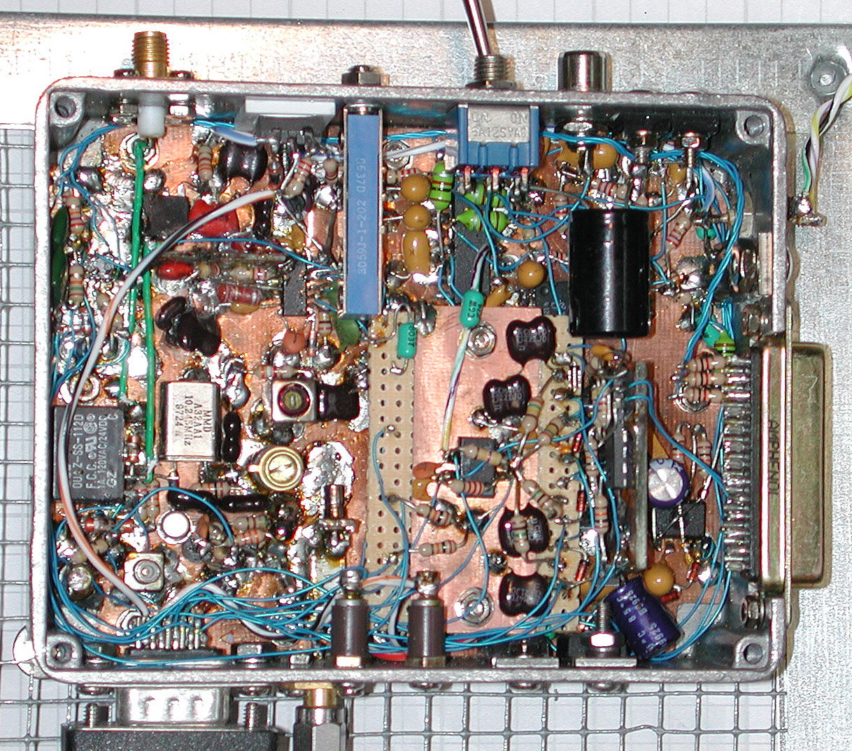 Among the more complex subsystems in the receiver, the WBFM demodulator/AF assembly lives at the end of the Equinox signal chain. Here, the 10.7-MHz
IF signal from the third converter is switched with a relay between an SA604AD-based FM IF
strip for WBFM demodulation and a fourth mixer stage. The latter is responsible for downconverting the
signal to 455 kHz in all other modes (AM, NBFM, and SSB/CW). A 10.245-MHz crystal oscillator
provides LO injection to the TUF-3 mixer near the DB-15 jack at bottom where the 455-kHz
IF strip is connected.
Among the more complex subsystems in the receiver, the WBFM demodulator/AF assembly lives at the end of the Equinox signal chain. Here, the 10.7-MHz
IF signal from the third converter is switched with a relay between an SA604AD-based FM IF
strip for WBFM demodulation and a fourth mixer stage. The latter is responsible for downconverting the
signal to 455 kHz in all other modes (AM, NBFM, and SSB/CW). A 10.245-MHz crystal oscillator
provides LO injection to the TUF-3 mixer near the DB-15 jack at bottom where the 455-kHz
IF strip is connected.
Prior to the fourth mixer stage, two SMB jacks (barely visible in the cluttered environs of the demodulator assembly) route the 10.7 MHz IF signal through a pair of ECS 10.7-15-B monolithic crystal filters, visible in their own subassembly at right. This filter provides a high degree of selectivity in NBFM and AM modes, and prefilters SSB/CW signals on their way to the Collins mechanical filter (below).
Since the output of the demodulator assembly is fed directly to the Mini-ITX motherboard for digitization and transmission at a fixed line level, neither the power amplifier section nor the DCA chip is particularly critical. Like the controller's high-stability clock, they are "legacy" features that were implemented before Equinox's client-server architecture.
This module is also responsible for gathering received signal-strength indication (RSSI) voltage levels from the MC1350P and SA604AD AGC loops and making them available to the ATMega128 in the main receiver controller assembly. There, they are digitized by the CPU's on-chip ADC and converted to dBm-based values for transmission to the clients.
The RSSI-to-dBm conversion process depends on the selected demodulation mode as well as the receiver frequency. To help with this task, a special-purpose client application fills a C++ header file with arrays of RSSI-to-dBm values that can be "baked" into the AVRCON controller firmware. This utility, CAL.EXE, works by harnessing an HP 8657A signal generator under GPIB control, commanding it to step through a series of frequency/amplitude combinations and recording the corresponding RSSI voltages observed in each of the four demodulation modes. It takes CAL.EXE about 30 minutes to build a complete calibration profile, resulting in several hundred reference entries that can be interpolated by the firmware to yield accuracy within approximately +/- 2 dB across most of the receiver's dynamic range.
Two other demodulator calibration adjustments are made manually through holes in the housing cover. The 10.245 MHz fourth LO is trimmed by observing its leakage into the 455-kHz IF path with a spectrum analyzer that can count the low-level signal. Nearby, the quadrature coil for the WBFM demodulator is adjusted for optimum symmetry. This is done by feeding an FM carrier with a 1-kHz test tone into the receiver's antenna jack and adjusting the slug to minimize even-order harmonics of the test tone in the recovered audio.
 Finally, all signals other than wideband FM are amplified and demodulated in the 455-kHz fourth IF strip,
shown at right.
Finally, all signals other than wideband FM are amplified and demodulated in the 455-kHz fourth IF strip,
shown at right.
The design of the 455-kHz IF section is best described as "traditional," especially in comparison to modern DSP-based receivers. Two MC1350P IF amplifier ICs provide gain in the AM and SSB/CW signal paths, using a hang-AGC circuit adapted from Hayward & DeMaw's original Solid State Design for the Radio Amateur. The SSB/CW product detector is a TI SN76514N double-balanced mixer, driven by the AD9850-based DDS BFO in the second-converter assembly. AM signals are demodulated by a simple half-wave rectifier, with AF and IF buffering provided by an LMH6644 quad opamp. Meanwhile, NBFM signals are processed by a Philips SA604AD in the lower-right portion of the assembly.
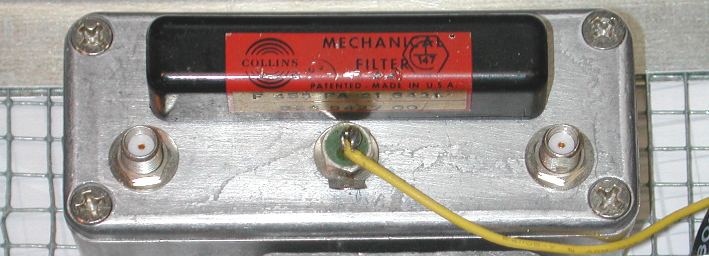 Additional selectivity in the SSB/CW signal path is provided by a 1964-vintage Collins mechanical filter.
SSB/CW performance is not a primary goal for Equinox -- imagine trying to work 40 meters with
no front-end selectivity! -- but the mechanical filter's old-school vibe was impossible to resist.
With careful impedance matching, its performance is superb (see graph at right).