Updated October 2, 2000: K3PGP has reported success in using Alpha Gunnplexers without varactor diodes in his 10 Mb/sec link. See Technical Correspondence for more information.
Contents
Photographs
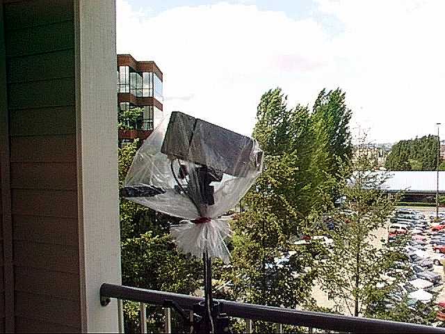
- Transceiver unit mounted atop a tripod on apartment balcony
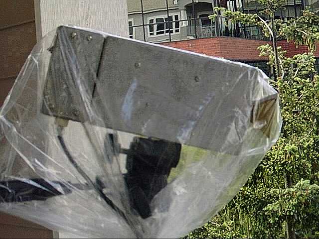
- A closer view of the tripod-mounted unit, showing separate chassis for modulator and receiver circuits
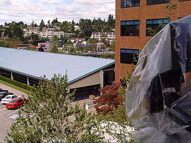
- Signal path, approximately 50 meters. Remote unit is located inside office by wooden crate on sidewalk.
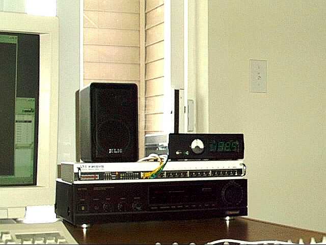
- Link control unit with its associated 10BaseT hub
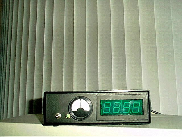
- A closer view of the link control unit, showing signal-strength and tuning indicators
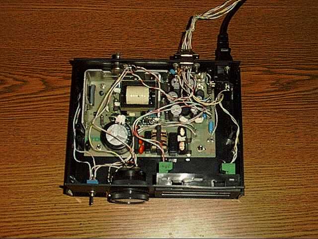
- Inside the link control unit, showing power supply and meter wiring
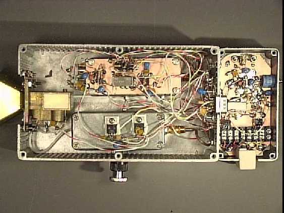
- Inside the transceiver unit, with subassembly covers in place
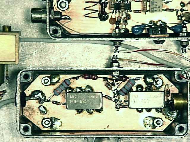
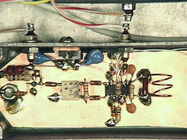
- Inside the IF amplifier subassembly, revealing MAR-6 MMICs and filters
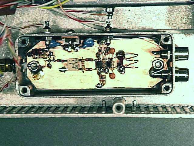
- Inside the MC13155-based FSK demodulator subassembly
- A closer view of the MC13155 and its associated components
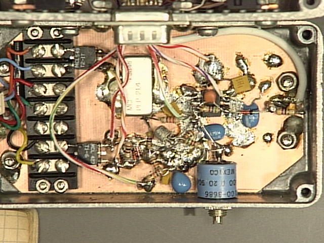
- Inside the Ethernet AUI interface and Gunn varactor modulator subchassis
Waveforms
- Ethernet signal as transmitted from AUI Tx port, before filtering and amplification
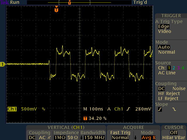
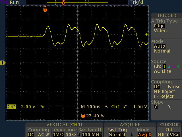
- Amplified and filtered Ethernet signal as applied to Gunnplexer varactor diode
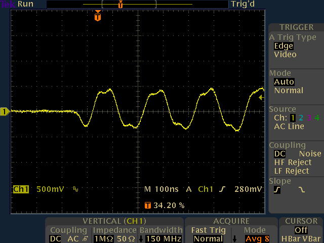
- Received Ethernet signal as delivered to AUI Rx port, after demodulation and filtering
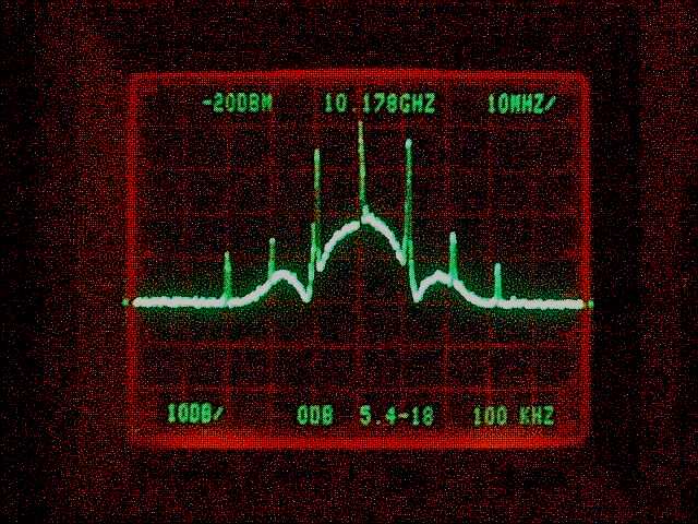
- Spectrum analysis of 10.178 GHz output from Gunnplexer, modulated by 10-Mbit/s Ethernet traffic
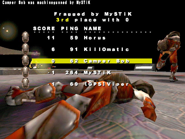
- Qualitative indication of excessive packet loss in early prototype
Schematics
PC Boards
- PC board design (untested, courtesy of Luis Yanes EB7GWL -- all comments regarding these boards should be directed to Luis)
It's ironic that some of the most exciting development work in high-speed data communications within the Amateur Radio community was carried out many years before the birth of the World Wide Web and the popularization of the Internet as a vehicle for mass communication. As a case in point, N6GN's pioneering 2-Mbit/s microwave data link was first described in 1989. A decade later, everyone and his mother-in-law is chatting happily away on the packet-switched, ubiquitously-connected communications network we call the Internet, but little progress has been made towards realizing the benefits of high-speed data networking in the Amateur Radio realm.
My own purpose in developing a 10-megabit radio link was threefold: to explore the design techniques underlying high-bandwidth microwave communications; to do my part to help bring Amateur Radio into the twenty-first century; and, most important of all, to use my company's T-1 Internet service at home for free. :-) This page is intended to describe my work to fellow Amateurs and other experimenters for whom a 9600-bps packet BBS or 31-baud PSK rig just doesn't cut it.
I've tried to describe the circuit and relevant construction techniques in depth, for those who may be interested in reproducing and/or modifying my work, but it should be made clear at the outset that such a project isn't a weekend endeavor for the electronics neophyte. While this isn't the most complex or demanding of projects, it has several unforgiving aspects that will not tolerate sloppy construction practices or inadequate care on the builder's part. You should be conversant with basic RF theory and construction skills before tackling it, or at least have access to one or two Elmers who have "been there and done that." You must have access to some basic electronic test equipment, including at a minimum a good oscilloscope and digital VOM. Finally, you should be prepared to commit the necessary resources of time and money to get the results you want. Underestimating the effort and expense required to get your project up and running is probably the #1 cause of failure.
System Architecture and Limitations
The data radio described here has certain limitations that may make it unsuitable for use in certain applications. It's extremely important to understand the microwave link's limitations and overall architecture before assuming that it will work well in your situation. If your application meets the following criteria, there's a good chance that this is the project you've been looking for!
In the following discussion, refer to the system block diagram and overhead view to learn how the transceiver modules are interconnected.
Although dish antennas are clearly the best choice when maximum range is the goal, they aren't likely to be necessary for links which span
less than a mile (1.6 km) or so. The prototype transceivers use homemade horn antennas fabricated according to a 1:1-scale template generated by Paul Wade, N1BWT's
excellent HDL_ANT antenna-design program. Here are two ready-to-build designs suitable for use with the M/A-Com 10 GHz and
24 GHz Gunn transceivers, respectively. Initial testing and alignment of the link can be accomplished with
no antennas at all, but unless you are contemplating extremely close-range work (less than a hundred feet or so with no obstructions) you will want
to fabricate horn antennas for your transceivers. You should observe about 5 dBi (i.e., 5 dB of gain over an isotropic radiator in free space) with the "naked" Gunnplexer
apertures alone, and about 8-10 dB of additional gain with the 15 dBi 10 GHz horn mentioned above. To construct each horn as shown in the
photo, I used sheet brass obtained from a local hobby shop, scoring the inner seams with a Dremel tool to allow the antenna to be
folded together origami-style, and soldered the remaining seam. There were plenty of leftover scraps available for mounting the antenna to the Gunn transceiver aperture.
It's important to achieve a tight fit between the antenna and aperture -- don't let the small end of the horn "float" too far off the Gunnplexer's mounting surface.
N1BWT's latest page has a great deal of knowledge in store for those who are interested in optimizing microwave antenna
performance, especially his online Microwave Antenna Book.
The financially well-endowed may choose to go with a commercial standard-gain horn antenna such as the HWR-90 model sold by Microtech, Inc.,
but their price of U.S. $400 each will likely send most experimenters reaching for their dust mask, safety goggles, and Dremel tool instead.
In addition to the 10 GHz devices mentioned above, SHF Microwave also distributes 24 GHz Gunn transceivers. These units are essentially identical to the 10 GHz devices used
in the link, and can be substituted with no circuit modifications. They are less expensive as well. However, they are quite a bit smaller
and somewhat less powerful (5 mW versus 10 mW) than their 10 GHz counterparts. I used a pair of the 24 GHz Gunnplexers in my initial experiments while developing
the radio link earlier this year, but found that the signal they emitted was attenuated too severely by the glass window at the "office" end of the link. The 10 GHz Gunnplexers had
no problem putting a good signal through the glass, especially after I upgraded them to the 100 mW Gunn diodes! Not being especially talented at metalworking, I also found it easier to fabricate
the larger horn antennas for the 10 GHz units. Finally, there are plenty of reasonably-inexpensive spectrum analyzers available on the surplus market, including my own Tektronix 492,
that make it trivial to set the 10 GHz Gunnplexers to any desired frequency. 24 GHz spectrum analyzers, on the other hand, still seem to cost about as much as a new Porsche.
All in all, I prefer the 10 GHz Gunnplexers to the 24 GHz parts and recommend them as a first choice if you don't have any
particular reason for wanting to run your link on 24 GHz. From what Alan is reporting, it appears that both models will continue to be available in the foreseeable future.
Data sheets for the 10 GHz and 24 GHz Gunnplexers are available here. Alan has annotated the 24 GHz model's data sheet
to clarify the misleading pin nomenclature used by M/A-Com. As with any sensitive microwave semiconductor device, it's vital to keep static electricity away from
the various Gunnplexer diodes, especially the mixer diode. These units come with shorting straps that should not be removed until you've soldered the 2.2K mixer
load resistor into place between the mixer diode and ground terminals. Don't apply power until you've checked and double-checked your pin connections!
I will attempt to keep this page up to date with any new information that comes to light on the availability of suitable transceiver modules. Please email me if you're aware
of any other sources for Gunn transceivers. (See the Technical Correspondence section for a link to a potential way to use cheaper surplus Gunnplexers that don't include varactor diodes.)
While the Mini-Circuits filters are relatively inexpensive, they could easily be replaced with homemade filters similar to N6GN's, if you have the
equipment to test them. Several basic filter-design programs can be found on the net, including Bob Lombardi's FilDes for MS-DOS.
One important distinction between the IF strip shown here and the N6GN design is the presence of a Mini-Circuits
T4-1 broadband transformer between
the Gunnplexer's mixer diode and the first MAR-6 amplifier. The purpose of this transformer is to provide a better match between
the relatively high-impedance mixer diode and the 50-ohm MMIC input. Without it, the effective receiver noise figure is
degraded by several dB due to excessive mixer-diode loading. The difference in weak-signal recovery performance is dramatic. It's surprising that the original N6GN article didn't include this useful tweak.
Besides the MC13155, the other key component in the FSK demodulator is the quadrature tank circuit. This is a parallel LC resonant circuit
(visible to the right of the MC13155 IC in the picture) which is tuned to the 145 MHz IF center frequency. As the
FSK-modulated IF signal varies above and below the center frequency, the quadrature tank circuit exhibits a varying amount of
phase shift which the MC13155 interprets to determine the correct output logic level. Because the 10-Mbit/s data rate requires a high signal
bandwidth for efficient transmission, it's necessary to deliberately lower the Q factor of the quadrature tank circuit to approximately 3.6 by
"swamping" it with a 180-ohm resistor. The resulting demodulation bandwidth is given by (145 / 3.6), or approximately 40 MHz. A signal near 125 MHz will yield a low output level from the MC13155,
while a signal near 165 MHz will result in a high output level. The center IF frequency of 145 MHz corresponds to the baseline Ethernet signal level which is present when no data is being transmitted.
Guidelines for alignment and testing of the FSK demodulator circuit appear below.
The filtered signal is then applied to a second OPA603 for amplification to a level which is compatible with the Ethernet AUI port. Note that this is still an "analog" signal
in every sense of the word -- it has not passed through any comparators or logic gates on either the transmitter or the receiver side of the link. Keeping the Ethernet signal in the analog realm by processing it with linear circuitry ensures that we are able
to preserve all of the edge characteristics of the signal as it transitions to and from the "neutral" state at the beginning and end of each packet. Experience has shown that Ethernet devices can be finicky about edge-preservation,
so our intention is to avoid potential edge-handling complications by leaving the job of digital signal conditioning up to the Ethernet hardware itself.
The output buffer circuit is fairly straightforward, with the exception of the 938-ohm resistor that controls the DC offset at the output of the first OPA603 op-amp. As the
schematic's notes suggest, this resistance value can be obtained with a parallel combination of 1K and 15K resistors, or with a 10-turn precision trimmer. In either case,
a good digital VOM can help you obtain a resistance value close to 938 ohms, either by hand-selecting 1K and 15K resistors which yield a total resistance within 1% of the desired value
or by presetting the trimmer adjustment. The idea is to position the output Ethernet signal at pin 6 of the final OPA603 to a baseline value close to 0V DC when no signal
modulation is present. Keeping the average DC voltage near 0V helps avoid core saturation in the Mini-Circuits T1-1
broadband transformer which is used for isolation between the transceiver and Ethernet device. Small changes in the 938-ohm resistor's value can yield large shifts in the average DC output level, so it
makes sense to strive for precision in this part of the circuit. You may wish to verify the DC offset of the output waveform with an oscilloscope, to make sure
the baseline level is within 100 mV or so of 0 VDC. The same unmodulated 145-MHz signal source used to align the FSK demodulator (below) can make the output buffer offset
easy to tweak as well.
In any event, you should resist the temptation to use AC coupling in lieu of the DC level-shifting components in either the output buffer or FSK modulator circuits. Ethernet packet traffic
appears as a series of periodic signal bursts with widely-varying duty cycles. Capacitors used for AC coupling between stages with different DC operating points (such as between the MC13155 and
the output buffer amplifier, or between the AUI transmit circuit and the Gunnplexer varactor diode) inevitably introduce an RC time constant characteristic which can cause the average
DC signal level to vary over time, both between and during packet bursts. Because of the aforementioned sensitivity of Ethernet hardware to the integrity of signal edges at
the beginning and end of each packet, any component which introduces a time-variant DC characteristic is bound to be a bad thing.
In fact, this effect cost me several weeks of head-scratching and an astonishing amount of money during development of the prototype link. I found I could receive either low-duty-cycle pings or continuous high-intensity
traffic near 10 Mbits/s, depending on the AC-coupled circuit characteristics -- but I was never able to find a configuration that would allow both types of traffic to pass! Given the complexities of choosing the filters, amplifiers,
signal levels, deviation and bandwidth figures, and other operating conditions at both ends of the link, this was one problem I did not need. (Most of the R&D budget for the project went straight to Tektronix for one of their
nifty new digital-phosphor oscilloscopes, which, in desperation, I convinced myself I needed in order to track down the link's signal-integrity problems. :-)
It should also be noted here that the AUI ports on the Ethernet hubs I used were not enabled by default. Some experimentation revealed that the hubs would not
recognize an attached AUI transceiver unless all of the ground pins on the AUI port were tied together to signal the presence of a device plugged into
the port. As the schematic indicates, pins 1, 8, 11, and 14 should be bonded together at the AUI plug. Because the AUI signals themselves are differential in nature,
this ground connection does not need to be connected to the transceiver ground at either end. I have heard vague rumors that some manufacturers' AUI ports also expect to
see at least a few milliamps' worth of loading at their +12V output pins in order to recognize the presence of a connected transceiver device. This was not the case
with the LinkSys hubs I used, but may be worth investigating further if you are unable to get the link working in your case. It is easy enough to verify AUI-to-AUI connectivity with
a 4-wire crossover cable (pins 3-5 and 10-12 joined at both ends) if you have doubts about your ability to communicate with your particular hubs or NICs. Please email me
if you are able to verify or dispute any of these observations with respect to the AUI interface.
The Ethernet signal to be transmitted enters the modulator circuit through a Mini-Circuits T2-1T broadband
transformer, configured as a balun to provide isolation and an improved impedance match between the 78-ohm AUI port and the Mini-Circuits
PLP-21.4 low-pass filter which follows it. By Carson's Rule, the bandwidth occupied by a transmitted FM signal is
related to the highest modulating frequency present. Consequently, the low-pass filter is employed to eliminate high-frequency energy present in the Ethernet waveform which would otherwise waste
bandwidth without carrying useful information.
After filtering, the Ethernet signal is amplified by a Burr-Brown OPA603 wideband current-feedback op-amp. The variable resistor R1 controls the amplifier's gain,
which determines the amplitude of the output waveform applied to the Gunn varactor diode and, consequently, the deviation of the transmitted
FSK signal, or the magnitude of its excursions from its center frequency. At the OPA603's output, a 1N4148 diode provides cheap insurance against possible damage to the
Gunnplexer varactor caused by forward-bias transients when powering the link up or down.
When designing a frequency-shift-keyed transmitter such as this one, the desired FM deviation is typically chosen on the basis of the highest
modulating frequency expected to be transmitted. The deviation ratio, given by the ratio of these two values, is not particularly critical, as
long as it is sufficient to generate intelligence-bearing sidebands of reasonable amplitude, without occupying an unnecessarily-large chunk of bandwidth.
A deviation ratio between 1 and 2 is typical for such applications. One reason the exact deviation ratio isn't critical is that a precise, optimal transmission bandwidth budget is tricky to calculate for a complex waveform such as an Ethernet signal,
or even a voice transmission. Prior to being used to modulate an FM transmitter, most of the energy in a 10-Mbit/s Manchester-encoded baseband Ethernet signal exists around the 10 MHz point, falling off several megahertz
to either side. Very little signal-bearing energy remains by the time our 21.4-MHz low-pass filter cutoff frequency is reached, so the filter's purpose is largely to eliminate harmonics
generated in the process of forming the Ethernet waveform.
For those interested in a more detailed look at the subject, W6QS has posted an excellent, easy-to-follow graphical model of 10-Mbit/s Ethernet and its FSK modulation characteristics at the
Tech Bench Elmers Amateur Radio Society page.
Finally, an actual spectrum-analyzer screen shot of the FM-modulated 10 GHz signal from one
of the prototype transceivers appears here. This particular snapshot was taken while several megabytes' worth of MP3 files were being
copied from one end of the link to the other at full Ethernet speed.
Fortunately, because the relative frequency separation between the two transceiver units is more important than their absolute frequencies,
any such drift-compensation circuit needs to be implemented at only one end of the link, not both. In our case, the output buffer circuit at the
"low-frequency" (10.178 GHz) end of the link has a few extra parts. A low-gain amplifier consisting of one stage from an
LM324 quad op-amp is connected to monitor the differential outputs from pins 4 and 5 of the MC13155 FSK demodulator,
with its output fed via a low-pass RC integrating filter and bipolar transistor buffer to a voltage-summing junction in the FSK modulator circuit. The OPA603 in the FSK modulator
circuit adds the constant voltage at its inverting input to the output signal it delivers to the Gunnplexer varactor. (Because the sign of the added voltage is inverted
by the OPA603, we apply a negative voltage to the summing junction to yield a positive bias offset at the varactor.)
The result is a simple feedback loop, in which any difference in the DC level between the two FSK demodulator output pins is amplified, integrated over
time, and used to steer the IF difference frequency in the proper direction to cancel out the unwanted offset voltage. The filter circuit, consisting
of a 4.7 uF capacitor and a 10K series resistor, is necessary to keep the AFC loop from trying to cancel out the desired rapid changes in frequency
arising from the normal Ethernet modulation process.
At the other end of the link -- the "high-frequency" end which operates at 10.323 GHz -- we simply feed the modulator summing junction with -8 volts through a fixed 820-ohm resistor, resulting in a constant DC offset
of about +5V. This is enough to bias the varactor diode into a reasonably-linear portion of its voltage-versus-frequency characteristic curve, while providing sufficient headroom on both sides for
the applied Ethernet modulation. If the Gunn varactor diode or its associated driving circuitry exhibits any drift, the AFC circuit at the other end of the link will adjust its own
Gunnplexer's center frequency to compensate. The distinction between the two transceivers is arbitrary -- note that we could just as easily have applied AFC correction at the
high-frequency transceiver unit instead, swapping the connections between the MC13155 and LM324 to change the sign of the correction signal.
With one transceiver mounted indoors and kept at a relatively constant temperature of 75 degrees F, this AFC mechanism has proven capable of
maintaining the integrity of the link at Gunnplexer temperatures between approximately 50 and 140 degrees F as measured at the outdoor end of the link. Beyond 140 F, the system ran out of
compensation range and failed. The excessive heat buildup was due to the effect of the outdoor unit's near-airtight RF shielding on a particularly warm day, aggravated by the use of
plastic wrap for rainproofing. A small fan was installed in the transceiver's outer housing to aid ventilation, eliminating further problems.
In the prototype unit, this meter actually serves as a power-supply current monitor in addition to monitoring the AFC circuit. The meter, installed at the
link control box, uses the 15' power-supply ground line as its DC signal path return. Instead of a conventional zero-center tuning meter as a frequency indicator, I used a
0-100 uA full-scale meter, with a separate sensitivity control that adjusts the meter for a center-scale reading under normal power-supply load conditions. Any
fault condition with the Gunn diode or other portion of the system with substantial current requirements will deflect the meter off-center. This dual-purpose
monitoring scheme was a good match for the full-scale 0-100 uA meter I had on hand, since the current drain from the optional 100 mW Gunn diode I used was
sufficient to drive the meter to center scale under normal operating conditons. In reproducing the project, you may elect to use a standard zero-center tuning meter with a separate signal ground line, or even omit the meter circuit entirely.
The prototype transceivers use a pair of
Extech 390GVS2 meters, available from Future-Active Electronics. This digital
panel meter is designed for direct readout of applied voltages between 0 and 200 mV, so a resistive voltage divider is used to bring the amplified voltage from
the S-meter buffer back down to the meter's display range. The resistor values shown will yield a displayed voltage within a few millivolts of the
actual RSSI output from the FSK demodulator subassembly.
In one prototype unit, the following S-meter values were observed and charted next to the actual voltage measured at the FSK demodulator subassembly's RSSI output connection.
The negative S-meter readings at low RF levels are due to a combination of the LM324 buffer's offset voltage and the voltage drop along the
transceiver power cable's ground lead, the latter being dominated by the substantial negative current consumed by the Gunn diode. The input signal was an
unmodulated 145.0 MHz carrier applied at the input of the MAR-4 IF buffer amplifier.
The prototype's threshold of data recovery was approximately -45 dBm at the FSK demodulator subassembly input. In general, any S-meter indication below 20
or so corresponds to a signal level which is too low for reliable operation. The signal path depicted in the photo yields S-meter readings around 35-40 with the
optional 100 mW Gunn diodes installed in the M/A-Com 10 GHz transceiver modules, suggesting a usable S/N margin of about 10 dB. (The IF strip's gain of 40 dB can be
added to the levels shown above to determine the signal available at the Gunnplexer mixer diode for a given S-meter reading.)
Like the tuning/fault meter circuit, the exact design of the signal-strength monitoring circuit can be left to the builder's
discretion. Omitting the S-meter circuit isn't recommended, as it is almost indispensible for antenna aiming and link diagnostics.
Signal Level
Displayed S-meter indication
Actual RSSI voltage in mV
IF power in dBm
(No signal)
-5.0
2.4
-60
-4.6
2.8
-55
-3.6
3.8
-50
0.0
6.8
-45
8.0
15
-40
20
25
-35
28
33
-30
38
42
-25
50
53
-20
60
63
-15
65
68
-10
68
70
-5
70
72
0
72
74
Apart from the output voltages available from the main power supply, the transceiver subassemblies require power busses at +9, +/-5, and -8 VDC. These voltages are
easy to obtain from 3-terminal 78/79xx regulators driven from the main power supply. (The +5V supply to the MC13155 is derived from a dedicated 7805 regulator inside
the FSK demodulator subassembly). To keep the diagrams simple, none of the 3-terminal regulators and their associated bypass capacitors
are shown on the schematics, although they can be seen in the overall view of the prototype transceiver assembly if you
look closely. Two regulators are mounted on the cover of the IF strip subassembly, with the remaining pair mounted to either side of the 9-pin
D-sub connector where the power supply and signal-monitoring cable from the link control unit plugs in.
Because the microwave link is a broadband system with very high gain, good RF shielding and decoupling practices are quite important when assembling
the transceiver units. While it's not necessary to follow the prototype examples faithfully in every respect, a few general suggestions are worth pointing out.
Perhaps the most important advice of all is to study the manufacturer's data sheets and app notes for the parts you plan to use, even if you don't understand
everything being discussed. The manufacturer's application engineers have seen every problem under the sun, and it's in their interest to warn you about
potential complications that are likely to arise when working with their chips.
The most convenient order of construction and testing of the transceiver subassemblies will be determined by your available test equipment. A basic handheld frequency counter from Radio Shack or Optoelectronics will make it easier to adjust the Gunnplexers' mechanical tuning screws, for example. Similarly, even an inexpensive RF signal generator such as the Elenco SG-9000 or older HP608-series model can be used to put the FSK demodulators on frequency. In general, the less test equipment you have, the more time and patience you'll need.
In soldering to the Gunnplexer diode terminals, it's best to use a very hot iron with a small, well-tinned tip to keep from "soaking" the diodes with excessive heat. A low-wattage iron
brings with it a greater risk of damage to solid-state devices, since it will take longer to make a good connection. A grounded iron suitable for
use with static-sensitive devices is ideal, if one is available.
Next, apply +5V DC to each Gunnplexer's varactor diode to establish the voltage corresponding to the center IF frequency. It's best to feed this
voltage through a temporary network consisting of a 10K resistor followed by a 0.1 uF bypass capacitor, to keep power-supply noise from complicating
the alignment process. If you have access to a microwave spectrum analyzer or frequency counter, simply adjust the Gunnplexers' mechanical tuning screws
to set one unit to 10.323 GHz and the other to 10.178 GHz. Again, the exact frequencies are not critical as long as they are within a few MHz of 145 MHz apart.
Keep track of which unit is which -- you'll need to install the 10.178 GHz Gunnplexer into the "low-frequency" transceiver to maintain the correct Ethernet signal polarity.
If you don't have a way to measure the Gunnplexer output frequencies directly, you'll need to monitor the mixer output of one unit to measure the
difference in their frequencies. With both mixer-diode shorting straps in place, carefully solder a 2.2K resistor between the mixer
terminal of one Gunnplexer and its ground terminal. The shorting strap on this unit may now be removed. Separate the two Gunnplexers by a few inches,
with their apertures facing each other, and connect a VHF frequency counter, spectrum analyzer, or receiver to the mixer terminal. Slowly tighten either Gunnplexer's tuning screw into its resonant cavity
until a difference frequency of 145 MHz is received. This will appear as a quieting signal on a 2M receiver. To make sure you're in the 10.0 - 10.5 GHz amateur band,
you may wish to tighten the screw on the other Gunnplexer at this point until the same result is achieved. Clockwise rotation of the tuning screw will
lower the transmitted frequency. Since the Gunnplexers' initial frequency as delivered from the factory is close to 10.525 GHz, this two-step process should
put your units safely within the ham band. Should you find your units hopelessly misaligned, an inexpensive police radar detector with X-band capability can help you
retune them to a frequency near 10.525 GHz. Radar detectors typically respond to a range of frequencies around 60 MHz either side of 10.525 GHz, so you
should be able to achieve a good center-frequency response with the tuning screws.
As an alternative means of alignment, if you have access to a 145 MHz signal source (either a 2M rig or a calibrated RF signal generator) you may find it
more convenient to build and align the FSK demodulator assemblies first. Temporarily connect one of the demodulator assemblies to the mixer diode test point. (The IF strip
will not be needed for close-range testing.) The output voltage between pins 4 and 5 of the MC13155 will pass through 0V as the difference frequency between
the two Gunnplexers passes through 145 MHz. In fact, this makes a good sanity check even if you have already aligned the Gunnplexers by other means. Watch out
for false nulls -- the response at the correct adjustment point should be sharp and symmetrical to either side.
An accurate 145 MHz signal source should be used for final alignment of each FSK demodulator circuit. This can be a 2M transmitter operating on the bench a few
inches away from the circuit under test, a calibrated signal generator, or even an aligned pair of Gunnplexers. The latter option can be especially attractive since a
good frequency match between the Gunnplexers' IF difference frequency and each FSK discriminator's tank circuit is exactly what we're trying to achieve.
With the signal source turned on, use a digital VOM or oscilloscope to monitor the differential voltage between pins 4 and 5 of the MC13155. It's easy to connect a
monitoring instrument if you route these signals to a pair of RCA jacks, as in the prototype. Spread or compress the coil's turns by hand,
using a toothpick or other nonmetallic alignment tool, in order to minimize the voltage difference between the two pins. Your goal should be to come within +/- 10 to 20 millivolts
of 0V. Fine adjustment can be accomplished by physically bending the leads of the 180-ohm resistor or 22-pF capacitor to move the component's body back and forth relative to
the coil.
Finally, remove the alignment tool and install the FSK demodulator subassembly's cover to ensure that the coil's tuning characteristics don't change drastically
with the cover in place. If a marked change in alignment occurs, remove the cover and separate the coil's turns slightly to compensate.
If you have a 50-ohm signal generator with a calibrated output attenuator, you may wish to check the amplitude response at each demodulator assembly's RSSI output against the
table above. RSSI output values within +/- 20% should be noted at each input level setting.
Links which are constructed with substantially different microwave transceiver modules, or which need to be carefully optimized for
maximum S/N performance, should employ a variable resistor at R1 to simplify calibration. If you have an oscilloscope with a 50-100 MHz bandwidth, it would
definitely be a good idea to verify that your LO drive waveform is similar to the prototype's in amplitude and DC offset with actual
Ethernet data being transmitted. Since I do not have a copy of the official Ethernet specification to work with, I'm assuming that wide variations in AUI output
amplitude are not likely to show up among different manufacturers' hubs and network interface cards! As always, I'd appreciate any feedback regarding this issue.
Most of these sources have already been mentioned above, but are listed here for ease of reference.
Some of my favorite related links (a few of which I've mentioned elsewhere):
A couple of pointers to good books appear below. In particular, if you are about to start building this project and you haven't read Bob Pease's
excellent Troubleshooting Analog Circuits, stop reading this and go buy it! I am not eager to hear from thousands of frustrated builders who somehow expect
me to do a better job explaining what's wrong with their circuit than Bob can. :-)
RF Safety and Regulatory Issues
It's impossible to cite specific guidelines for regulatory compliance in every national and local jurisdiction where this microwave radio link may be constructed and operated, so I won't spend much time on the topic. In the United States, a holder of a valid Technician-class or higher Amateur Radio license may operate an FSK data link between 10 and 10.5 GHz for noncommercial purposes. Here, "noncommercial" implies a purpose which does not involve direct financial gain on the operator's part. This rule has been the subject of recent liberalization. Using a personal Internet link to telecommute with your office or buy books from amazon.com would be unlikely to arouse the FCC's ire, but operating an ISP or e-commerce site might be pushing it. In jurisdictions with specific station-identification requirements, a modulated CW subcarrier could easily be applied to the transmitted signal at narrow-band deviations substantially lower than the modulated signal used for data communications. In any event, I do not condone or recommend illegal or unlicensed operation of this or any other radio transmitter in any jurisdiction, for any purpose. This site cannot be considered a source of legal advice on any application of this project. Further, I expressly disclaim all responsibility for criminal or civil liability incurred by anyone who constructs and operates the microwave link in violation of applicable law.
Now that we're past all the mandatory disclaimers, the reality is that as an operator of an X- or K-band data link, you are far more likely to be the victim than the cause of any interference to other radio services. Especially in urban areas, these bands are heavily populated by users ranging from supermarket door-openers, to microwave burglar alarms, to police traffic radar units -- all of which operate at frequencies and power levels which are similar to those used by the link. It is hardly an uncommon occurrence to find these users operating with unstabilized Gunnplexers which have long since drifted out of their assigned frequency slots and into the 10-10.5 GHz ham band. With good directional antennas on your link, operating near the minimum power necessary for reliable communications, the odds that you will cause harmful interference to any other service are essentially nil. However, you may need to be prepared to adjust your Gunnplexer tuning screws as necessary to move your link as far away as possible from any interfering sources. As noted above, if you can solve this type of problem by throwing more antenna gain at it, by all means do so! Like other FM radios, the microwave link will exhibit a "capture effect" which will tend to block interference from other signals arriving at the receiver with substantially less power relative to the desired carrier. A good antenna system can make all the difference when faced with interference from off-axis sources.
Finally, although power levels associated with Gunnplexers tend to be low enough to disregard from a health-and-safety standpoint, it's still a good habit to refrain from peering into an operating
feed horn or antenna aperture, no matter how low the power. Don't install microwave antennas where uninformed parties (children, pets, inquisitive visitors...) are
likely to do the same.
Acknowledgements
Kirkland, Washington
August 9, 1999
John, may I suggest a small change in ur schematic? Now, you are allowing the 2.2K load on the mixer to be in parallel with the 4:1 transformer. Not bad, but protection can be equal and a bit more signal found if you do it the way I indicate on the attached .pdf drawing, called mixer2.pdf...
Thanks to Alan for this suggestion. There's certainly no reason why the mixer diode's DC load resistor can't be placed in series with the matching-transformer primary.
I have corrected the error in the FSK modulator schematic, and will fix the corresponding Orcad file as soon as possible.
I had guessed what you were thinking when you put the AFC together pretty well and I think it will work, but not as well as the tweaked circuit. I'm sure neither are really optimum in any sense of the word though. The reason I still like mine a tad better is that I measured the actual varactor voltage as I heated the gunnplexor on one end up with the heat gun. For your circuit I could notice almost no change in the voltage at the collector of the 2N2222 or at the varactor diode either one. With the 2N2222 in the active region I can see it change by several volts in the right direction. It is probably the case that the 2N2222 here happened to have a higher beta than yours did, and so works not so well in your circuit. I like to think of my circuit with the 2N2222 as a voltage to current converter, and think of the current as driving the op amp. At least for me, having the BJT in the active region with its more linear behaviour makes the feedback range much greater than having it most of the time in the saturated mode. Any feedback system should work better with a higher loop gain, as long as it is still stable.
I haven't encountered any trouble of this nature with the prototype, but if you're having problems achieving robust operation of the AFC circuit in your link, give Rob's modification a try!