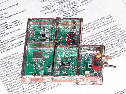
There are worse ways to spend a weekend than being locked in a basement with a thousand watts' worth of RF test equipment, debugging a homebrew microwave synthesizer while putting some new phase-noise measurement software through its paces. This page bears the fruits of one such weekend's labors, which were devoted to measuring and improving the performance of the newly-released first LO boards for the "Scotty Spectrum Analyzer" project.
The SSA is a sophisticated yet economical instrument that covers the DC to 1 GHz spectrum with much better resolution and stability than offered by any of the so-called "poor man's spectrum analyzer" projects made from salvaged CATV tuners. Its first local oscillator is a hybrid synthesizer similar in topology to the KE5FX/VK6BRO synthesizer project. A direct digital synthesizer -- in this case, the Analog Devices AD9850 -- serves as a fine-tuning reference source for a simple integer-N PLL based on the National Semiconductor LMX2326. Noise and spurs are attenuated by a crystal filter between the DDS and PLL sections.
As of this writing (August 2005), the SSA is also very much a work in progress.
Cash Olsen, KD5SSJ has devoted
considerable effort to creating a professional-quality reproducible project based on
Scotty Sprowls's prototype. Only someone with a bottomless junk box
is likely to be able to duplicate Scotty's work exactly, but Cash's PC boards go a long way toward bringing the
SSA magic to the masses.
Having just wrapped up the first release of my new phase-noise measurement application, I found myself looking for a few good test subjects. So I volunteered to help characterize the performance of Cash's new boards.
Like the antenna, first mixer, and, well, just about every other part of
a good receiver, the first LO is absolutely critical for overall system performance.
This is as true in spectrum analysis as it is in any other receiving application. A spectrum analyzer can't measure the composite noise
level of a source unless its own local oscillator(s) are quieter than the source itself. Likewise,
spurious signals in the LO output will appear around every signal the analyzer sees.
Laboratory-quality analyzers tend to be free of significant spurs above at least 70-80 dB down from a carrier displayed at reference level. A serious homebrew effort should be able to play in the same ballpark. In the noise department, an analyzer such as the SSA is unlikely to compete with a commercial model based on a YIG oscillator... but it's still necessary to make sure that the synthesizer's noise profile is within the expected boundaries given the technology at hand.
PLL simulation tools are valuable for optimizing both
noise and spur performance, but they can never eliminate the need to scrutinize the performance
of a real-world model. If you didn't measure it, you don't know it. PLLs, in
particular, are never short on surprises!
Hacking the Software
It wasn't hard to modify the control application for the KE5FX/VK6BRO synthesizer to work with Cash's boards. The AD9852 DDS driver code was replaced with code for the (much simpler) AD9850 chip, and a new microsecond-precise timer was added to help benchmark lock-time performance.
Like the original KE5FX code, the new SSASYNTH C++ class is compatible with both Win32 applications and embedded applications compiled with AVR-GCC for the Atmel AVR platform.
Download control/test software for Win32 and Atmel, including full source code
| PLL Connector Pin | PC LPT Pin | Atmel AVR Port | Function |
|---|---|---|---|
| 9 | 6 | Px2 | AD9850_DATA |
| 4 | 7 | Px3 | AD9850_CLK |
| 3 | 8 | Px4 | AD9850_LATCH |
| 5 | 4 | Px5 | PLL_LATCH |
| 10 | 2 | Px6 | PLL_DATA |
| 6 | 3 | Px7 | PLL_CLK |
| 12 | 15 | Px0 | PLL_LOCKED (Optional) |
| 1 | 18-25 | GND | GND |
The table at left describes the wiring between the connector on Cash's PLL assembly and the PC parallel port used by the modified KE5FX control software. Your connections may vary -- be sure to check your PLL connector wiring by comparing functional pin assignments rather than pin numbers.
As delivered, my PLL assembly did not break out the lock-enable signal from pin 14 of the LMX2326 chip. I routed
it through pin 12 of the SSA LO assembly connector so that the software could display the lock time in microseconds
via the ERROR input (pin 15) of the LPT port.
If you don't make the same change to your hardware, you may need to connect pin 15 of the LPT port to +5V so the software won't wait forever the loop to lock. (You can also change the #define WAIT_FOR_LOCK statement near the beginning of stest.cpp from 1 to 0.)
Observing the Symptoms
 The good news was that the modified control software worked perfectly the first time. But
the HP 8566B analyzer I was using to test the board delivered different news altogether.
The good news was that the modified control software worked perfectly the first time. But
the HP 8566B analyzer I was using to test the board delivered different news altogether.
As the blue trace reveals in the graph at right, the synthesizer assembly as tested "out of the box" had some major spur problems. A few hours of troubleshooting via signal-substitution revealed three independent causes, listed in order of severity:
- Phase truncation of the DDS signal The board is clocked at 64 MHz by an onboard
crystal oscillator. The DDS divides this signal by a factor of roughly 5.98 to generate the
PLL reference signal near 10.7 MHz. Since 5.98x is very close to 6x, the
"remainder" spur at an offset of 200 kHz (i.e., 6x10.7 MHz - 64 MHz) is strong enough to make it through the
crystal filter assembly, either via direct feedthrough, radiated/conducted leakage, or both. Like
other reference-derived spurs, it is amplified by 40-50 dB by the PLL multiplication process,
and it can be seen here at only about 20 dB down from the 1200 MHz carrier peak.
This spur can be reduced or eliminated by moving it farther outside the loop bandwidth. At first glance, it appears that the loop bandwidth must be narrowed, or a different clock frequency must be selected that's not so close to an integer multiple of 10.7 MHz. But are these really the right strategies? Read on for the exciting conclusion.
- Inadequate reference suppression Examination of the phase-noise plot (below) and
simulation of the PLL with its existing component values revealed that the loop bandwidth was
approximately 60 kHz. I used a reference divisor of 11 in my software, yielding a comparison
frequency of about 973 kHz. Although the simulation suggested that the reference spurs should
be down at least -65 dBc, they actually showed up at around -32 dBc in the real-world hardware,
with strong second harmonics at about -54 dBc. The reason for the discrepancy isn't clear,
given that the subassemblies in Cash's synthesizer are reasonably well-shielded and
decoupled, especially after I soldered copper foil tape across every edge of the
double-sided PCB shield partitions.
You can actually see the 200-kHz phase-truncation artifacts on the reference spurs in the blue trace. Even the spurs have spurs. :-) It appears that the remedy is, again, a narrower loop bandwidth. But first impressions don't always tell the whole story!
- Reference-interval EMI I noticed this peculiar effect when developing the KE5FX/VK6BRO hybrid
synthesizer, but was never able to find any mention of it in the literature. In a nutshell, the ADF/LMX PLL chips,
and possibly others, are sensitive to radiated or conducted emissions at frequencies near multiples of
their internal comparison frequency. In this case, we can see some artifacts near 500 kHz and
1500 kHz offsets that originate in DDS and/or clock-related EMI at 10.7 MHz plus
or minus (N * 973 kHz). The nasty part is that the (N * 973 kHz) term can range from DC to near
100 MHz.
Given a wide-enough loop bandwidth, it's almost impossible to find a master-clock frequency that doesn't cause noticeable spurs due to this effect. The use of a high-gain amplifier or comparator in the reference signal path makes the problem even worse. Once again, in the absence of discrete, milspec-quality enclosures for each PLL subassembly, it seems that the only way to combat these spurs is to reduce the loop bandwidth.
A First Attempt ...
The purple trace above was taken under the same conditions as the blue trace, but after the installation of a narrower loop filter. Overall loop bandwidth was reduced from approximately 60 kHz to approximately 9 kHz for this experiment... and wow, what a difference! The phase-truncation spurs and reference spurs are now over 40 dB lower, and the EMI problem is gone altogether. It's no longer present even in the green trace, which is a two-minute sweep taken at a much lower resolution bandwidth to look for anything else that might be hiding near the noise floor. Bonding the shield layers together with copper tape did help a little, but the only real improvement I could make to Scotty's and Cash's design was the reduction in loop bandwidth.
What are the downsides to reduced loop bandwidth? There are two potential drawbacks -- lock time, and close-in phase noise peaking. Here, you can see two graphs taken with a DSO at the VCO tuning line as the synthesizer is stepped across its entire range, from 1000 MHz to 2000 MHz:
It takes almost 30 times longer for the loop to stabilize when its bandwidth is decreased from 60 kHz to 9 kHz. The phase-noise plot also reveals a bit more noise near the critical 10-12 kHz channel-spacing interval where VCO performance is commonly measured:
 This schematic, generated by the fantastic (and free) ADIsimPLL simulator from Analog Devices,
shows the component values for the 9.3-kHz loop filter used in these experiments. Once you've installed
ADIsimPLL, you can download the following two files to compare the original and modified versions of the loop.
This schematic, generated by the fantastic (and free) ADIsimPLL simulator from Analog Devices,
shows the component values for the 9.3-kHz loop filter used in these experiments. Once you've installed
ADIsimPLL, you can download the following two files to compare the original and modified versions of the loop.
60-kHz PLL as implemented by original KD5SSJ boards
But What's the Real Problem?
In my initial draft of this page, I stated:
Paradoxically, I believe the best strategy for SSA constructors who are after the ultimate in performance is to use an even narrower loop bandwidth. Why? Well, the improvements in spur performance gained with the 9.3-kHz filter are dramatic, but the synthesizer still isn't quite as clean as I'd like. When constructed with the recommended 1500-2000 Hz loop bandwidth, the KE5FX/VK6BRO synthesizer exhibits better spurious-free dynamic range by at least 10 dB under most circumstances. I don't see any reason why the SSA synthesizer can't achieve similar performance.Was the answer really as simple as reducing the loop bandwidth? Well, not exactly. There were still a few nagging issues.In fact, the lower-power AD9850 chip may even be responsible for the improvement in close-in noise at < 3 kHz offsets relative to the KE5FX design in the plot above. A long-term automated spur search will be necessary to see if the 14-bit AD9852 DDS is really earning its keep in the KE5FX design, relative to the cheaper 10-bit AD9850 chosen by Scotty. (Watch this space!)
Lock time is largely a non-issue in this application. The reason is apparent from a close examination of the screenshot of the Win32 console app running above: incremental frequency changes, of the sort made by a sweeping spectrum analyzer, are still very fast.
With the 9.3 kHz loop filter used here, the PLL needs about 100 uS to relock after a 10-MHz step. It takes that long just to program the hardware. 100 MHz steps, larger than the SSA will ever need to execute, require only about 200 uS. Finally, 1-MHz steps, which would be used to plot a full 1-GHz spectrum across 1,000 pixels, take place so quickly that the program never has a chance to detect the unlocked condition.
It seems reasonable to expect that loop bandwidths in the 2-kHz neighborhood will yield further improvement in the analyzer's SFDR and phase noise specifications without impacting sweep time significantly.
- First, why were the reference (and other) spurs so much worse than predicted by simulation? Nobody with any design experience is surprised when reality refuses to conform to a simulation, but in this case, the discrepancies were ludicrous.
- And why was the amplitude of many of the spurs affected by the signal level at the input of the comparator? I'd observed this effect in my initial testing with a substitute signal generator, but didn't consider it significant enough to mention or otherwise follow up.
- The biggest question of all was one that simply couldn't be hand-waved away or blamed on a questionable simulator. Scotty's prototype SSA synthesizer used an almost-identical loop filter. So why didn't his synthesizer exhibit all those spurs?
 The last question came up on the SSA Yahoo group immediately after I
stated my case for a drastic reduction in the loop bandwidth. I didn't have a good answer. Speculation centered around
Cash's use of toroidal transformers as part of the crystal filter matching network, and the PCB layout associated with them. Were
we seeing DDS spur leakage around the crystal filter due to mutual coupling between the toroids? It didn't seem likely due to the
self-shielding properties of toroidal inductors in general. But another group member, Sam Wetterlin, made a post that opened a very
interesting avenue of investigation:
The last question came up on the SSA Yahoo group immediately after I
stated my case for a drastic reduction in the loop bandwidth. I didn't have a good answer. Speculation centered around
Cash's use of toroidal transformers as part of the crystal filter matching network, and the PCB layout associated with them. Were
we seeing DDS spur leakage around the crystal filter due to mutual coupling between the toroids? It didn't seem likely due to the
self-shielding properties of toroidal inductors in general. But another group member, Sam Wetterlin, made a post that opened a very
interesting avenue of investigation:Hi John,Not only would Sam's suggestion eliminate any possibility of coupling between the two toroids, but it would address the second of the "nagging questions" I mentioned above. I replaced the second toroid with a 0.1 uF coupling capacitor, followed by a 3K load resistor between the comparator input pins. The results of a tracking-generator sweep at the input pin were enlightening (see graph at right, with all traces normalized to the same peak level).I had sent an email to Cash suggesting that he simply delete the second toroid, which comes out of of the (crystal) filter. Since the comparator input is high impedance, the desired impedance can be set by a shunt resistor to ground. This will also get 6x as much voltage to the comparator.
Blue trace: Original toroid pair
Green trace: Both toroids replaced with Mini-Circuits T36-1 broadband transformers
Purple trace: Final toroid replaced with 3K resistive load
It was easy to see that there was, indeed, some leakage due to coupling between the toroids and/or their associated leads. The
crystal filter's spurious response at 200 kHz was undoubtedly not a good thing for the DDS phase-truncation artifact. But
what was even more interesting was the effect of the missing toroid on the signal amplitude at the comparator input. The
signal level across the 3K resistor was now about 0.5V peak-to-peak, which not only improved in-band phase noise a good deal, but eliminated the 200 kHz phase truncation spur
from the PLL output entirely!
A follow-up post from Scotty points out why it's a bad idea to rely on the comparator to provide a large amount of voltage gain:
... There is a phenomenon that occurs in hard limiters that many people don't know about. When an input signal is hard limited, any other frequency that is at least 10 dB lower than the highest input signal will be somewhat attenuated (squashed). ... I have seen spurs attenuated by as much as 20 dB, depending on the amount of hard limiting.The benefits obtained by increasing the signal at the comparator input on Cash's board are unmistakable. And they lead to the question... was the wideband loop response really such a bad thing after all?
Back to the Wideband Filter...?
 After removing the second toroid, it made sense to try a wide loop filter again to see how much responsibility the
marginal signal level at the comparator input bore for the synthesizer's original spur problem. The 973-kHz reference spur wasn't
affected by the modification, of course, since it originated further downstream in the PLL chip itself. But what about the rest?
After removing the second toroid, it made sense to try a wide loop filter again to see how much responsibility the
marginal signal level at the comparator input bore for the synthesizer's original spur problem. The 973-kHz reference spur wasn't
affected by the modification, of course, since it originated further downstream in the PLL chip itself. But what about the rest?
I went back to ADISimPLL and designed a filter that would raise the loop's bandwidth to 65 kHz, a figure even wider than Cash and
Scotty's original design. (The 0603-scale SMD components from Cash's original loop filter had long since vanished into the
carpet beneath the workbench, but I did verify that the new filter's output spectrum with both toroids in place
was similar to the initial spur-infested graph above.)
65-kHz ADIsimPLL design
Next, I reapplied the 0.1 uF capacitor / 3K resistor modification. The 973-kHz reference spurs were worse than before, due to the wider
loop filter... but the rest were gone!
It seemed reasonable to blame excessive op-amp input bias current for at least part of the synthesizer's failure to live up to the
reference-spur suppression figures predicted by ADIsimPLL. This graph shows the effect of three different op-amps on the reference spurs with
the 65 kHz loop filter and 3K resistive filter termination in place:
Blue trace: Original opamp specified by Cash (TI TLE2141CD)
Green trace: Analog Devices AD8510A/B
Purple trace: Linear Technology LT1677
The results are telling: the TLE2141CD performs poorly in both the input current and noise departments. The LT1677 and AD8510 are both much better choices. The AD8510's ultra-low input bias current figure of 25 pA drops the first (973-kHz) reference spur by almost 35 dB relative to the TLE2141CD!
However, the LT1677's superior noise specs enable it to outperform
both competitors at offsets greater than 1 MHz. These figures were obtained without cleaning flux from the PCB or taking any other
measures to reduce leakage currents, so they are probably far from the best-case performance levels obtainable.
All three opamps perform similarly at offsets below 500 kHz, but the AD8510's lower 973-kHz spur makes it look (artificially)
quieter towards the 1 MHz end of the graph below:
Final Measurements and Conclusions
An automated test series of the synthesizer at 2800 randomly-selected frequencies between 1000 and 1800 MHz reveals no
significant spurs at offsets beyond a few kHz.
This graph shows a 500-kHz wide chunk of RF spectrum surrounding each of the randomly-chosen carrier frequencies. It was taken with the 3K resistive termination mod and the 65 kHz(!) loop filter with an LT1677 opamp.
With the 65 kHz filter, observed lock time from 1000-2000 MHz is approximately 50 microseconds. This is much faster than necessary, and even with the AD8510, the 973-kHz reference spur is still objectionable with such a wide loop bandwidth.
Consequently, the ideal loop
bandwidth for the SSA synthesizer would likely be somewhere in the 20 kHz range. A value in this neighborhood should yield fast lock times and
near-complete freedom from spurs and other "surprises."
Finally, the graph at left was made by sweeping the KD5SSJ synthesizer from 1000 to 2000
MHz. Flatness appears to be +/- 2.5 dB relative to the 9.75-dBm level measured at 1500 MHz.
This graph has been corrected for analyzer and interconnect flatness.