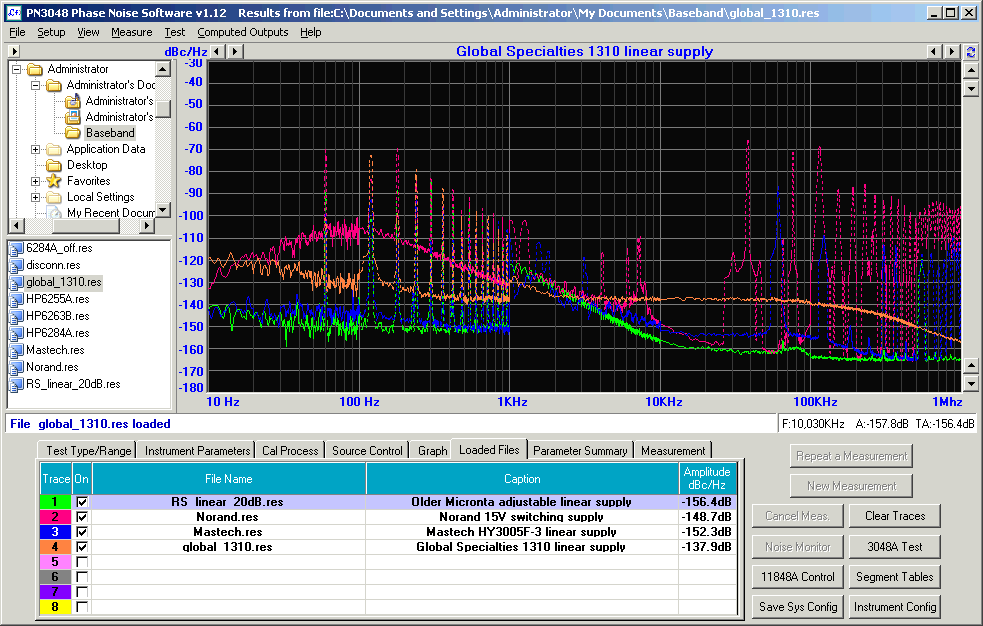
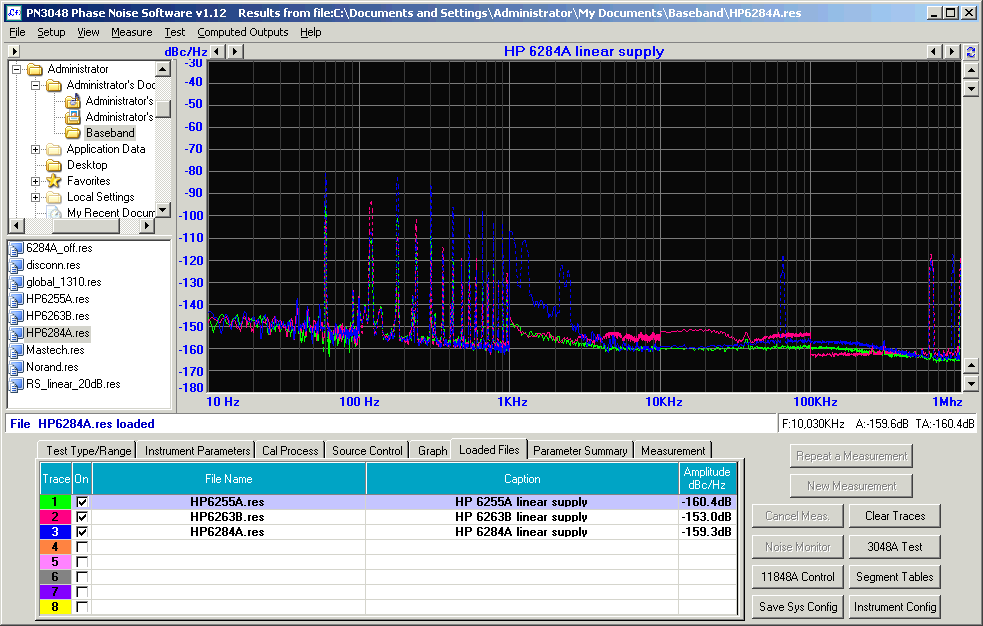
Non-HP linear supplies (plus a Norand 15-volt switching supply):
Note inability of HP 3561A FFT analyzer to resolve spurs in the 1-10 kHz decade; this may be fixable with segment-table optimizations. There's also an unexplained 10-dB discontinuity in the HP 6263B's trace at 100 kHz, which was repeatable with that supply but not with any of the others.
While the three-terminal and Darlington regulators were tested with a resistive load, the bench supplies were tested driving a 12-volt relay winding, so some of the low-frequency spurious content may be due to stray AC field response on the part of the relay coil. Coupling to the HP 11848A's 50-ohm baseband noise input was achieved via parallel 0.15 uF tantalum/22 uF aluminum electrolytic capacitors, followed by a 20 dB attenuator (HP 355D). The resulting 3-dB corner frequency is 120 Hz.
Graph scales are in dB below 1 volt RMS (Sv(f) [dBv/Hz] vs. f[Hz]), normalized to 1 Hz bandwidth. For example, -140 dBv/Hz equals 10^(-140/20) volts, or 100 nv/Hz. To generalize this figure to equivalent input noise, multiply by the square root of the system bandwidth. 100 nv/Hz of Gaussian noise in a 1-kHz bandwidth would correspond to approximately 3.2 uv on a true-RMS indicator, neglecting any noise-equivalent scale factors that might apply to the original bandwidth calculation.
A similar relationship can be expressed in terms of power: since 0 dBm = 224 mv RMS in a 50-ohm system, 1 v RMS is +13 dBm, and 100 nv/Hz would equal -127 dBm/Hz. (Note that 'root-Hz' is now just 'Hz', since power is proportional to voltage squared and sqrt(1 Hz) = 1 Hz.)
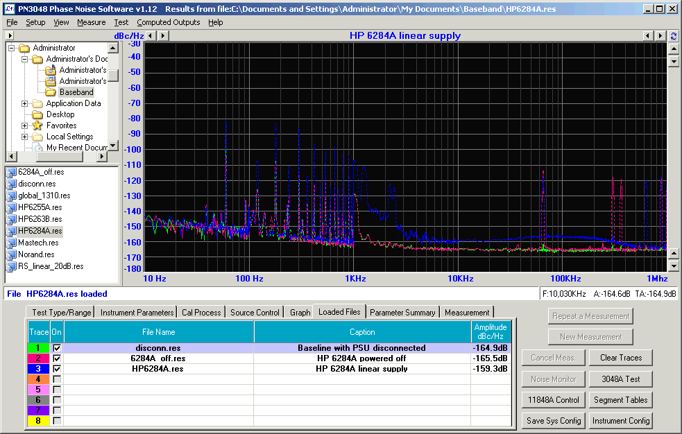
The green trace below represents the measurement floor with the DC block/relay coil disconnected from any supplies. Again, 20 dB of range is lost due to the attenuator.
At 1.4 uV/root-Hz or -117 dBv/Hz, Steve's measurement of the LM317 sans Radj bypass is a good match for the -137 dBv/Hz figure seen in the green trace in the first plot, allowing for the 20 dB attenuator. I really need to revisit these measurements with a better test setup...
A bit more on the subject from Jason Breitbarth of Holzworth Instrumentation on Marki Microwave's blog.
LDO Noise Examined in Detail, Masashi Nogawa, TI
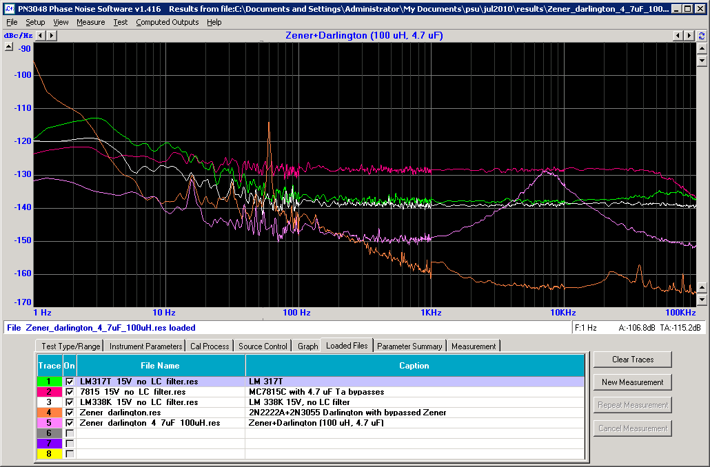
Errol Dietz's Reduce Noise in Voltage Regulators discusses the origin of the noise peak as a consequence of resonant interaction between the load capacitance and the regulator's inductive output impedance. Nice example of output impedance measurement with an HP 3577 LF network analyzer.