FAQ and Troubleshooting Hints
Q. Where can the current version of the GPIB Toolkit be downloaded?
A. http://www.ke5fx.com/gpib/setup.exe will always point to the latest version.
I'd recommend against mirroring this file, since bug fixes and enhancements are made
on a regular basis. Please link to this copy instead, using the ke5fx.com address rather than any redirected URLs where the
setup file may be hosted.
Q. What are all these .PLT, .SSM, and .PNP files for? I just want to save screenshots!
A. .PLT, .SSM, and .PNP files are the "native" formats used by 7470.EXE, SSM.EXE, and PN.EXE, respectively. While
all three of these programs can save screenshots to .GIF, .PCX, .BMP, and .TGA files, you are almost always
better off saving most of your acquisition data in the application's native format, and 'rendering' screen captures only when
needed for publication.
Why? The answer depends on the application. 7470.EXE allows you to load multiple HP-GL/2 (.PLT) files at once and overlay them
for easy visual comparison with each other, rendering them at any of several screen resolutions. None of these features are
possible if you saved only .GIF, .BMP, .TGA, or .PCX image files for your previous measurements, because 7470.EXE can't read
those formats.
The same is true of PN.EXE. Phase-noise plot files (.PNP) contain much more data than is visible in
a given screenshot. If you don't keep copies of your original .PNP files, you won't be able to overlay multiple noise plots,
choose different legend fields, or render your plots at different resolutions. Likewise, .SSM files allow you to scroll through hours' or days' worth of real-time trace data, much
more than a single screen capture can represent.
So you should always save "native" files for measurements you want to keep. You can
turn them into screenshots anytime!
Q. Can any of the Toolkit applications save screen images to .JPG files?
A. No. .JPG files use lossy compression techniques that have been optimized for photographic subjects. They're not
appropriate for saving high-contrast vector images, graticule plots, or any other form of line art.
.GIF files will make
your PN and 7470 screen captures look better, and they'll often be smaller as well. The .GIF format can also be used to store
SSM screenshots, but .BMPs are preferable due to the larger color space needed to represent a saved SSM display.
Q. Is there any way to get .CSV trace data out of 7470.EXE?
A. Not directly. 7470.EXE generally doesn't have access to the raw measurement data that the instrument uses to compose its HP-GL/2 plots. However, there are several third-party data conversion utilities that may be helpful. Save your plot to a .gif, and
try WebPlotDigitizer, for example. (That link no longer works as of 3/2026, but LLMs do the job nicely as long as you take the time to verify the result.)
Q. Any tips for running the Toolkit applications under Linux?
A. Some users have reported good results using the WINE compatibility layer.
It's important to note that each of these tools was written -- usually in a hurry -- in response to a need I've encountered in my own work. They're not meant to be
polished commercial-quality applications, and they often play fast and loose with current best practices in professional Windows development. In fact, many of
the GPIB Toolkit programs are console apps that run in a "DOS box," so even experienced Windows users may find them challenging to work with.
So to the extent that the GPIB Toolkit applications can be used in Linux or other non-Windows OSes, that's great, but I'm not able to offer much help if you have problems getting them to run. If you need one or more of these tools and you don't have the necessary skill (or luck) to
make them work in your OS of choice, I'd strongly recommend using them under Windows as intended. Ars longa, vita brevis, and it costs about $100 to buy a decent Windows laptop at a flea market these days.
Q. Where do 7470, PN, and SSM save the files they acquire?
A. Newly-acquired .PLT, .PNP, and .SSM files are saved in the so-called "current working directory" effective
at the time the program was started. If the current working directory is
found to be the Windows desktop or any directory in the Program Files tree, the current user's My Documents folder
is used instead.
In practice this means that quite a few temporary files are likely to accumulate in your My Documents folder.
You can force the programs to save their files to any desired directory -- except for those within the Program Files
tree -- by right-clicking on their shortcuts and changing the Start in: field.
Because the GPIB Toolkit programs can reuse or otherwise overwrite their own temporary files, it's always a
good idea to save your own copies of any files you want to keep.
Q. What GPIB adapters are recommended for use with the toolkit?
A. I've found the GPIB-USB-HS adapters from National Instruments to be extremely reliable, with several of them in daily use in my lab. These are commonly offered
on eBay in the $200 range from both US-based and Chinese sellers. Prior to adopting GPIB-USB-HS adapters for my own work, I used NI PCI-GPIB adapters with my desktop system and a Prologix adapter with my laptop. The
PCI-GPIB offers the best overall performance in realtime applications such as SSM.EXE, and its price on eBay
is typically about the same as a new Prologix board (US $125-$150), making it a good choice if you don't need
portability. Of course, a separate GPIB cable is required for use with a PCI-GPIB card, unlike the Prologix and GPIB-USB-HS solutions.
Important note: as of mid-2022, some of the newer GPIB-USB-HS adapters available on eBay have been found to cause error messages related to address assignment when using
7470.EXE to acquire host-requested plots. Try selecting GPIB->No assigned plotter address (listen only) if this occurs. (You can set default_board_addr to -1 in 7470.INI to make this
selection the default.)
One inexpensive GPIB-USB-HS clone in particular has been found to work with the HP 8753ES VNA, subject to the requirement to select GPIB->No assigned plotter address (listen only) for plotter emulation with 7470.EXE. This adapter is selling in the US $65 range as of this writing (July 2024).
Currently, only National Instruments and
Prologix adapters are "supported" by the GPIB Toolkit, in the sense that the code was written, and continues to be maintained, with these models in mind. There
are quite a few National Instruments-compatible adapters on the market, but in my experience they aren't always
as compatible with the NI 488.2 programming standard as their manufacturers claim. Prologix has also been targeted by Chinese copycats on occasion. Avoid third-party clones and counterfeits -- they simply aren't worth the
hassle.
While generally well-behaved with the Toolkit's various applications, one caveat with the Prologix adapters is that they don't get along well with the HP VNAs
supported by the toolkit's VNA.EXE application. They work, but timeout errors and other problems are common. VNA users are strongly encouraged to stick with NI
adapters, especially since they're supported by other useful VNA utilities such as CalKit Manager.
National Instruments also sells PCMCIA adapters. They work well, but they're more expensive than other adapters,
even on the used/surplus market, and OS compatiblity may be a concern. Most users should also avoid older National Instruments products such as the GPIB-232CT-A and PC II/IIa. These do
not support modern (NT-based) versions of Windows, and even if they plug into your current PC, they probably won't
work with your next one. Likewise, National Instruments' GPIB-ENET adapter is somewhat awkward to configure under Windows XP or later
versions of Windows (see below).
Q. Have any other GPIB adapters been tested with GPIB Toolkit applications?
A. The Alciom smart488 is an economical USB interface that's similar in some ways to the Prologix adapter.
It has been used to obtain device-initiated plots in 7470.EXE from the HP 8569B and other instruments.
This board also offers some basic GPIB controller capabilities; if you edit the CONNECT.INI file in your user data directory to set is_Prologix to 0, you may be able to use it
with the other GPIB Toolkit applications. Some experimentation will likely be necessary.
Keithley KUSB interfaces have also been successfully used for device-initiated plotting with 7470.EXE. As with the Agilent GPIB adapters mentioned below, NI488.2 compatibility drivers are required.
Q. Where can I find drivers for my GPIB adapter?
A. The NI488.2 driver package may be downloaded directly from National Instruments. This package is free, although
website registration is required. It includes the drivers for most of their GPIB adapters including their USB products, PCI-GPIB, and GPIB-ENET.
The Prologix GPIB-USB adapter requires the installation of drivers from the FTDI site. These VCP ("virtual COM port")
drivers enable communication with the Prologix adapter by simulating a standard RS-232 serial port.
Prologix GPIB-ETHERNET adapters don't require any drivers at all -- you just need to update CONNECT.INI to supply the
adapter's IP address and port. This can be done automatically in the GPIB Configurator program.
Q. I have an HP or Agilent GPIB adapter. Can I use it with the GPIB Toolkit?
A. Some Agilent adapters claim to support NI488.2 compatibility. Although I don't have any direct experience with
the compatibility layer, reports from users have been positive. Try
searching for "NI488.2" at http://www.agilent.com for further details.
One important note is that NI488.2 compatibility is not enabled by default. Until you enable NI488.2 compatibility in the Agilent/Keysight software, the adapter will not be available for selection in the GPIB configurator, and the
Toolkit will not work with it.
At least one user has indicated that the Agilent 82357A adapter works well with PN and SSM, and can
also acquire host-requested plots with 7470, throuh the NI488.2 compatibility layer provided by the
Agilent E2094Q I/O Libraries Suite 15.0
package. Device-initiated plotting did not appear to work properly with the 82357A in this case, and the
Agilent 82350 adapter was not usable at all.
Carlo Canziani of Agilent Technologies Italia S.p.A. reports:
I'm pleased to inform you that I tested your SW with Agilent interfaces GPIB/USB 82357B and LAN/GPIB E5810A.
Agilent libraries allow usage in NI-488.2 compatibility mode so can replace the NI interface without modifying (the GPIB Toolkit). Agilent Libraries can be downloaded from www.agilent.com/find/iolib.
Rick Griffiths has compiled a handy checklist (100 KB .PDF) of the exact steps needed to configure the Agilent I/O libraries for use with the GPIB Toolkit. He also notes that he was able to resolve
some inconsistent behavior when using the E4440A PSA spectrum analyzer and an 82357B adapter with PN.EXE by upgrading the Agilent I/O Libraries package to version 16.1.
Q. What about the S82357 adapter from Beiming Technologies?
A. The S82357 is a very economical GPIB-to-USB adapter that emulates the Agilent 82357B. All of the advice above applies to it -- as long as you install the latest
Agilent I/O Libraries suite and configure the adapter for "Agilent 488" support, the S82357 offers good NI488 compatibility in most applications. As with the Agilent adapter,
you may not be able to use device-initiated plotting in the 7470 emulator. Host-requested plots generally work well, though, as do most other GPIB Toolkit programs.
Q. Can I use an ICS GPIB adapter with the Toolkit?
A. SSM.EXE seems to work pretty well with the original ICS USB-to-GPIB adapters, but I've encountered lockup problems
(including driver-level crashes) in PN.EXE, and I haven't been able to get the newer 488-USB2 adapter working reliably at all. Make sure you've downloaded the latest drivers from ICS before
attempting to use the GPIB Toolkit with one of these adapters. Also, ensure that your ICS adapter's GPIB identifier matches the
interface_settings line in CONNECT.INI. By default, the Toolkit expects NI488.2-compatible adapters to be configured as GPIB0.
To request plots from instruments for use with 7470.EXE, it may be
necessary to use the command-line QUERY.EXE utility. As an example, the following lines may be included in a
batch file to acquire and render a plot from an HP 8566B or HP 8568B spectrum analyzer:
   query 18 "PLOT 250,250,10000,10000;" >test.plt
   7470 test.plt
This technique can come in handy with other GPIB interfaces that aren't quite 100% compatible with 7470.EXE.
Q. How can I use a National Instruments GPIB-ENET adapter under Windows XP or Vista?
A. The NI488.2 driver package does not support IP address configuration of the GPIB-ENET adapter under any version of Windows later than Windows 2000.
W2HX reports a workaround:
1) Turn off GPIB-ENET
2) Set all dip switches to "off"
3) Install RARPD from http://www.panix.com/~perin/rarpd.zip
4) Edit RARPD.TBL to include MAC of your ENET and the desired IP (for example 00.80.2F.FF.xx.xx.xx.xx 192.168.1.10)
5) Run rarpd.exe
6) Turn on GPIB-ENET
7) After some blinking, the Ready light should become stable; the IP address is now assigned
8) Turn off GPIB-ENET
9) Set dip switch 6 to ON, which causes the stored IP address to be used
10) Turn GPIB-ENET on
11)  Install NI488.2 software distribution from National Instruments website (OS-dependent)
It isn't known if this procedure will work under Windows Vista. Further info, courtesy Jim, AC0XU:1) The last version of NI-488.2 that supports the GPIB-ENET/100 is version 17.6.
It is still available from NI here. It supports various versions of Windows up to Win 10.
2) Versions of NI-488.2 that support the GPIB-ENET (original 10 Mbit device) are
available from NI's FTP website here.
Users should be aware that the NI drivers are inexplicably fussy
about DNS if you use DHCP. If you configure the GPIB converter
with a fixed IP address that is easier. The NI GPIB Ethernet
Wizard verifies that the device is online and the NI GpibConf.exe
utility can be used to assign the fixed IP address.
Q. I'm getting a GPIB error message as soon as I try to connect to an instrument. What's wrong?
 A. The GPIB Toolkit application is probably trying to talk to a National Instruments board that isn't there.
If you're using a Prologix adapter, have you edited the CONNECT.INI file to tell the
GPIB Toolkit where to find its virtual COM port? (Most users can simply run the GPIB Configurator program and
select the Update CONNECT.INI button after selecting their adapter's COM port from the list. Be sure to exit from the GPIB Configurator
before trying to run any other GPIB Toolkit applications.)
A. The GPIB Toolkit application is probably trying to talk to a National Instruments board that isn't there.
If you're using a Prologix adapter, have you edited the CONNECT.INI file to tell the
GPIB Toolkit where to find its virtual COM port? (Most users can simply run the GPIB Configurator program and
select the Update CONNECT.INI button after selecting their adapter's COM port from the list. Be sure to exit from the GPIB Configurator
before trying to run any other GPIB Toolkit applications.)
This error condition may also mean that you're trying to use an adapter that is not National Instruments-compatible. Only
genuine National Instruments and Prologix GPIB adapters are supported. When attempting to use Agilent adapters, make sure you enable their
NI488.2 compatibility feature in the Agilent Connection Expert utility.
Q. I'm getting the same error message when I try to use my National Instruments GPIB-ENET adapter.
A. The GPIB-ENET's device identifier defaults to GPIB1 in many installations. Edit the interface_settings line
in the CONNECT.INI file to reflect the correct device identifier, or run the GPIB Configurator utility.
Q. What other issues can occur when connecting to GPIB equipment?
A.
Always use the thumbscrews when installing GPIB hardware -- the connectors are heavy and tend to work loose sooner or later. It can
be hard to tell if the connectors on Prologix and other "dongle" adapters are seated properly unless you tighten them down.
Keep other equipment off the bus until you've
debugged your connection to the target instrument. This way, addressing conflicts or cabling problems with unrelated instruments won't complicate the troubleshooting
process.
Powered-off GPIB devices can load down the bus and cause timeouts or other errors, so the IEEE 488 specification calls for two-thirds of the devices on a given GPIB segment to be powered on. This prescription is
conservative in most cases, but there are some dramatic exceptions. For example, if even one of your
instruments is a powered-off HP 8656/8657 signal generator, you will probably not be able to talk to anything else on the bus.
Check the application's user guide for instrument-specific notes that you may have overlooked. For example,
the Tektronix 490/2750-series analyzers must have their LF-OR-EOI switches set to '1' for use with
the GPIB Toolkit applications. Tektronix 2780-series analyzers must have the corresponding menu option enabled.
Finally, use care when toggling DIP switches in older instruments that use them for talk/listen and address configuration.
You may need to use an ohmmeter to verify switch settings once all other problems have been ruled out.
Q. The GPIB Configurator is reporting the error, "This application has failed to start because NiSpyLog.dll was not found."
A. NISPYLOG.DLL file is a National Instruments file. In addition to enumerating Prologix GPIB-USB and GPIB-ETHERNET adapters,
the GPIB Configurator will also detect National Instruments adapters, making them available for selection. Error messages such as this one ordinarily mean that the drivers
for a previously-installed National Instruments GPIB adapter have not been completely removed.
If it's not practical to uninstall or reinstall the National Instruments driver files completely, you can run
the GPIB Configurator with the -noni command-line option to avoid attempting to access them.
Q. Should I configure my Prologix adapter for Device mode, or Controller mode?
A. Your adapter will need to be in Controller mode to run all of the GPIB Toolkit applications, except when
you're receiving device-initiated plots in 7470.EXE. In that mode, the application is acting like a GPIB "device,"
capable only of receiving and responding to traffic originating from an external instrument or controller.
SSM, PN, and the console applications rely on being able to initiate communication with the instrument, so they
require the Prologix board to be set to Controller mode.
Beginning with version 1.50 of the GPIB Toolkit, it's no longer necessary to use the GPIB Configurator or another terminal program
to switch your Prologix adapter between Device and Controller mode. Each Toolkit application will configure the Prologix adapter's
mode and address settings as necessary. If you're using a different
serial interface, or an older Prologix board that's not software-configurable, you'll need to set the CONNECT.INI is_Prologix field to 0. This will prevent
the Toolkit applications from issuing configuration commands to the board.
Device/controller mode selection is always performed automatically by the application when using an NI488.2-compatible board.
Q. My instrument has an RS-232 serial port rather than a GPIB port. Can I use the Toolkit with it?
A. In many cases, yes. The same code that supports virtual COM ports associated with Prologix adapters can also be
used to establish a direct serial connection. In addition to configuring your serial interface hardware appropriately, you
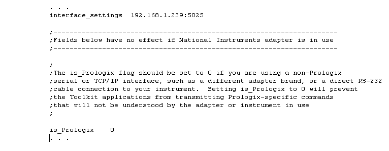
will also need to edit the CONNECT.INI file to set the is_Prologix field to 0 and modify the interface_settings string
as necessary based on the examples in CONNECT.INI's comment header. Setting is_Prologix to 0 will keep the GPIB Toolkit applications from trying to configure the GPIB adapter.
Note that when connecting directly to instrument serial or network ports in this fashion, the choice of GPIB address does not matter. Any address in the 1-30 range should work.
For the HP 8590E-series spectrum analyzers in particular, one user reports success with a CH340-based USB/RS232 converter. The baud rate was 57600 in his case, and the write_delay_ms parameter in connect.ini needed to be set to 200 ms.
Q. My instrument has an Ethernet port rather than a GPIB port. Can I use the Toolkit with it?
A. Network-based instruments can sometimes be used by editing the CONNECT.INI file manually. As in the FAQ above that
discusses direct RS-232 connections, you will need to edit the interface_settings string with a text editor and set is_Prologix to 0.
For example, Darren Storer, G7LWT/AK4DB reports that he was able to use SSM with his Agilent FieldFox N9914A handheld analyzer by
setting interface_settings to the instrument's IP address on his LAN (172.16.10.200:5025 in his case) and is_Prologix to 0. The FieldFox was then
usable with SSM by selecting Acquire->SCPI-compatible analyzer mode followed by Acquire->Acquire data from supported device at address 18.
(As when making direct RS-232 connections, the choice of GPIB address does not matter when addressing the instrument directly via TCP/IP.)
This technique also works very well with the Agilent E4406A transmitter tester, using port 5025. Note that E4406As with 2000-era firmware are known to
have problems with both Ethernet and GPIB-based communications, so you may need to upgrade the firmware if you encounter problems with either connection type.
Q. How can I use a Prologix GPIB-ETHERNET or other TCP/IP-compatible GPIB adapter that's located on a different subnet?
A. The GPIB Configurator utility will enumerate any GPIB-ETHERNET adapters on the local subnet. All you need to do to use the
GPIB Toolkit with a local GPIB-ETHERNET adapter is to highlight it in the configurator's list box and select Update CONNECT.INI. (If you see invalid IP
addresses such as [0.0.0.0] in the selection box, you will need to upgrade your copy of the GPIB Toolkit to the latest build.)
The GPIB Configurator cannot locate GPIB-ETHERNET adapters located at arbitrary corners of your corporate WAN or the Internet at large,
and it does not work with non-Prologix TCP/IP adapters at all. In these cases, you
will need to edit the CONNECT.INI file in your local data directory, placing the adapter's
IP address or DNS name in the interface_settings field.
If the address does not specify a port number (e.g., ke5fx.dyndns.org:1234), the GPIB Toolkit utilities will try to
connect to port 1234 by default. This port number is used by the Prologix GPIB-ETHERNET adapter.
As with non-Prologix serial interfaces, be sure to set the is_Prologix field to 0 if your TCP/IP
interface is not a Prologix GPIB-ETHERNET adapter. Otherwise, Prologix-specific configuration commands transmitted
by the GPIB Toolkit will be received by the connected instrument(s), causing errors or other undefined behavior.
Q. My Prologix adapter isn't working with my HP 8568A spectrum analyzer. What's wrong?
A. Lockups can happen when these analyzers are addressed to talk by the Prologix adapter following a ++loc (Return to Local) command
or other Prologix-specific ++ commands used by the GPIB Toolkit. As a workaround, you can edit the CONNECT.INI file
to set the reset_to_local field to 0. You may also need to avoid using the LCL button if resetting the
analyzer manually causes similar problems.
National Instruments adapters are not vulnerable to this problem with the HP 8566A-8568A analyzers, and it does not occur
at all with 'B'-suffix instruments.
Q. I'm able to request plots from my HP 8753 network analyzer with my Prologix adapter, but the instrument reports "Caution: Addressed to talk with nothing to say" as soon as I request the plot.
A. This problem is related to the HP 8566A-8568A issue above. Upon sending a ++loc command to reset the instrument to local operation after the
initial commands are transmitted by 7470, the Prologix board is addressing the instrument to talk. You may be able
to prevent this behavior by setting the reset_to_local line in CONNECT.INI to 0. (Of course, you'll have to press the LOCAL button before any further front-panel interaction with the analyzer.)
To take advantage of this change, you may also need to run the GPIB Configurator and ensure that the "Auto read after write" button is checked. Basically, as long as the adapter stays in auto-read mode and doesn't issue a ++loc command, you should be able to avoid
the error message. Some experimentation may be necessary.
Q. VNA.EXE seems prone to lockups with my Prologix adapter. What's wrong?
A. When controlled by modern PCs, the 1990s-era HP VNAs supported by VNA.EXE can run into timing and flow control problems under some conditions. VNA.EXE contains numerous patches and tweaks to
improve reliability with these instruments, but communication timeouts are still occasionally seen with Prologix adapters. The GPIB-USB adapter works well enough with VNA.EXE in most cases,
but the GPIB-ETHERNET is more prone to timeout issues. Overall, VNA.EXE tends to work most reliably with National Instruments adapters.
Additionally, you may find it helpful to use lower trace point
counts when saving .S2P files. Capturing 1601-point files from an 8753C with a GPIB-ETHERNET adapter will most likely fail, while the default 201-point traces are much more reliable.
Q. My HP 8753C doesn't work with 7470.EXE. The aspect ratio of the plot is incorrect.
A. Due to a firmware bug, some HP 8753-series analyzers may generate malformed plots in response to a request from 7470.EXE via the Acquire menu or the F9 keyboard shortcut. You may find it helpful to use the COPY->PLOT function instead, with 7470.EXE configured to 'w'ait for a device-initiated plot. The analyzer may need to be placed in System Controller mode, and 7470.EXE should be configured to emulate a plotter at address 5 via its GPIB menu.
See HP_8753_firmware_revision_history.pdf for more information about HP 8753A/B/C/D firmware issues.
Q. I'm able to request plots from my HP 8510 network analyzer with my Prologix adapter, but the instrument reports "Caution: No output type selected for HP-IB read" as soon as I request the plot.
A. As with the HP 8753 issue above, setting reset_to_local to 0 may take care of the problem.
Failing that, use genuine NI adapters with HP VNAs. Seriously. That's what I do.
Q. How can I recompile the GPIB Toolkit applications?
A. Download and install the free Microsoft Visual Studio Express package and the Platform SDK. Follow all directions carefully to
configure the MSVC command-line tools. The directions will vary substantially from one VS release to the next, so it's impossible to be more specific here. (No IDE project files are supplied, although you can create your own if desired.)
Once the path and other environment variables are set correctly, you should be able to run Visual Studio's nmake.exe utility from within the Toolkit's installation directory to recompile and link the executables. The makefile, C/C++ source files, header files, and resource scripts for all GPIB Toolkit apps can be found in the same installation directory where the executables are placed, while the GPIBLIB.DLL communications library sources are in the GPIBLIB subdirectory.
When building 'official' releases of the Toolkit, I use the command-line compiler from Visual Studio 2005 to maintain
compatibility of the generated executables with older Windows versions. So, depending on the Visual Studio version you use, it will likely be necessary to fix or otherwise work around various warnings and errors due to deprecation of older APIs and insecure CRTL functions.
Q. When I try to browse the readme or user guide .HTM files, Internet Explorer 7 warns me about "scripts or ActiveX controls that could access my computer." What does that mean?
A. It means that at least one or two undocumented vulnerabilities apparently remain in Microsoft's employee drug-testing policy. Rest assured, there are no scripts or ActiveX controls in any of the GPIB Toolkit's HTML help files.
I do not recommend using IE7 under any conditions; check out Firefox instead. This behavior also appears to have been corrected in IE8.
Q. I'm able to transmit plots to 7470.EXE, but I'm getting an error when I try to render them.
A. This problem is especially common with HP 8560-series portables. Make sure you've configured your analyzer to generate HP-GL/2 plots, and not Epson or other formats. 7470.EXE can only work with HP-GL/2
and PCL data. Also make sure the analyzer is in Talk/Listen mode (if you're requesting plots via the host PC) or Talk-Only mode (if you're
using its front-panel PLOT button).
If you're sure that you've received a valid .PLT file from a given instrument but you're still getting a rendering error, please send me the .PLT file for inspection!
Q. 7470.EXE is reporting errors such as 'Could not open plot0000.plt for writing' under Windows 10.
A. Here are some suggestions that have been helpful to other users:
- Run 7470.EXE with administrative privileges, or from an elevated DOS prompt
- Install the Toolkit in a directory that's not in the Program Files (x86) hierarchy, such as c:\gpib
- Right-click on the desktop shortcut and change the 'Start in' field to a directory that's not in the Program Files (x86) hierarchy
Q. I'm having trouble editing 7470.INI (or other files) in the installation folder. Changes don't seem to take effect. What's wrong?
A. As above, install the Toolkit in a directory that's not in the Program Files (x86) hierarchy, such as c:\gpib.
Q. How do the trace-resampling options in SATRACE.EXE and SSM work?
A. The key points are:
- When the trace is oversampled (i.e., when the number of source points is less than the number of requested points, such that each source point can contribute to one or more destination points), the only valid options are replication of trace amplitude values with the -points:xxx option or spline interpolation with -spline:xxx. The -min:xxx, -max:xxx, and -avg:xxx options are treated equivalently to -spline:xxx. (These command-line options are equivalent to SSM's Points menu selections.)
- When the trace is undersampled, meaning that at least some output points cover more than one source point, you can use -min:xxx, -max:xxx, and -avg:xxx to control how source "bins" are combined into output points. These are analogous to the positive-peak, negative-peak, and average detection options supported by the firmware in typical analyzers. You can also let the spline resampler decimate the source trace for you, which has the effect of averaging amplitudes across neighboring bins. Or you can just let the -point:xxx option arbitrarily pick one amplitude value from each bin, starting at the first point in the source trace.
- In all of these cases, the frequency values are linearly interpolated the same way. In the undersampling cases with SATRACE, frequency values always correspond to bin centers, while in the oversampling cases, the frequency is lerped across replicated points from the source trace. (SSM's frequency interpolation always begins at the left edge of the trace.)
- In no case are the amplitude values corrected for the analyzer's resolution bandwidth or changes in the number of points per span; they are merely interpolated, decimated, or selected from the source trace depending on the option selected.
Q. Can I use SSM with my HP 8563E ? I don't see an entry for it on the Acquire menu.
 A. The instruments that are specifically named on the Acquire menu in SSM are those that can't be autodetected with an ID? query.
As a result, you must select the correct "instrument mode" in the Acquire menu before you select the address of the instrument itself.
A. The instruments that are specifically named on the Acquire menu in SSM are those that can't be autodetected with an ID? query.
As a result, you must select the correct "instrument mode" in the Acquire menu before you select the address of the instrument itself.
The HP 856x/859x portables and 856xB benchtops don't have that problem, so you just need to tell SSM to start acquiring data from the
correct address. But if you had one of the 1970s-era 8566A/8567A/8568A behemoths, you would need to select the corresponding option first.
The same is true if you have a (much) newer SCPI-compatible model -- they use a different ID query (*IDN?), so
they also need a separate entry on the Acquire menu or a -scpi argument on the command line.
It's often helpful to add the GPIB address and other command-line options to your Windows shortcut, as shown in the example at right. You wouldn't use the -scpi option
with an 8560E-series analyzer (or with most other models that predate the E4400 series), but you can still include the address and other command-line options.
Q. Can I use SSM with my Keysight N9010B or other late-model instrument?
A. The N9010B has been reported as working with a GPIB connection with the Acquire->SCPI-compatible analyzer mode option selected (equivalent to using -scpi on the command line.) This may be true of other newer spectrum analyzers as well. Keep in mind that
many newer instruments support configurations and operating modes other than conventional RF spectrum analysis. It will be
necessary to set up your unit as a spectrum analyzer with a single active trace in order for SSM to work with it.
As with other models that include Ethernet ports, it may also be possible to use the N9010B with a direct LAN connection through the use of the 'Edit CONNECT.INI' option in the GPIB configurator. Performance can be substantially higher with a direct LAN connection. Settings similar to the following should
work, although the port number may vary from one instrument to the next:
If your initial connection attempts fail, look for options that support command-language compatibility with other SCPI models such as the Agilent PSA or R&S FSP that are known to be compatible with SSM.
Q. My HP 8560A/B/E- or 8590-series traces look strange in SSM.
A. In both SSM and SATRACE, some resampling operations can look better than others, or yield more-accurate results. SSM trace records are 640 points wide
by default, unless the Points menu or -n: command-line option has been used. Consequently, if you are acquiring data from an HP 8560A/B/E-series portable spectrum analyzer,
SSM has to resample the 601-point traces to 640 destination points. In such a case, the analyzer's default ("rosenfell") video detector output
can yield gaps or nulls at 16-pixel intervals due to aliasing effects. This is not usually harmful when observing CW signals,
but if your observed traces contain significant amounts of noise, it's a good idea to select sample or peak detection on the analyzer to avoid these artifacts.
For similar reasons, the spline resampler is not the best choice when viewing or acquiring traces containing frequency combs or other signals that yield fast
impulse-type video responses. Its low-pass filtering effect can artificially reduce the amplitude of comb signals, just as the analyzer's own video detector would
if averaging mode were selected.
In general, the resampling mode that yields the highest amplitude CW signals without introducing objectionable visual artifacts is the right one to use.
Q. Can I use PN.EXE to observe and record discrete spurs?
A. PN.EXE is not especially useful for observing spurs. Trace->Enable spur reduction can detect and remove spurs above a certain amplitude from the PN.EXE graph, but the program doesn't display them separately,
or list them with their correct (unnormalized) amplitudes the way other PN packages can.
In particular, spurs are not likely to be visible on the graph at wideband offsets. During noise acquisition, the trace data is point-sampled
by both the spectrum analyzer and PN.EXE. Within each decade, typically 500 to 1000 data points end up being displayed using 100 to 200 pixel columns at most.
For exampe, a spur in the 100 kHz-1 MHz decade may not occupy more than one point in the acquired data, assuming the analyzer sees it at all.
The odds that it will be visible on the final PN trace are low.
As a result, both 7470.EXE and SSM.EXE are better suited to observation and recording of spurs.
Q. Why doesn't PN.EXE support my particular spectrum analyzer model?
A. To measure phase noise at the offsets we're usually concerned about (1 kHz - 100 kHz from the carrier),
the spectrum analyzer needs to be accurately tunable at a corresponding degree of precision. In practice, that
means the analyzer needs to use synthesized tuning. Many older analyzers don't.
In addition, PN.EXE has to take control of the spectrum analyzer via GPIB, and it can't do that with analyzers
that are controlled only via physical switches on their front panel. Some of these analyzers allow you to
read their front-panel configuration via GPIB, but unless these settings can be programmed remotely, PN.EXE can't
work with them.
In other cases, it's simply a matter of not having access to the analyzer in question. I've focused on Tektronix
and HP equipment because that's what I own, but there are numerous other manufacturers (Advantest, R&S, Anritsu, IFR...)
that have also produced some excellent gear. If your analyzer model isn't supported by the GPIB Toolkit applications,
consider submitting a patch!
Q. Is it possible to use PN.EXE to determine the RF noise floor of the spectrum analyzer by making a measurement with no carrier present?
A.
Yes. PN.EXE doesn't really measure "phase noise," rather, it measures whatever combination of CW power and AM/PM noise contributes
to the observed trace amplitude. So in the absence of any signal to measure, it will show the RF noise floor, which should
be -174 dBm + 10*log(RBW) + whatever the analyzer's front-end noise figure is.
PN.EXE takes the 10*log(RBW) term out of the equation when it does its dBc/Hz normalization, so you don't have to worry about that.
However, it also subtracts out the reference level, so you would normally need to tell it to use 0 dBm as the carrier amplitude.
With most analyzers, though, the RF noise floor is so much lower than the PN floor that the existing carrier-clipping options
aren't adequate to get the noise floor out of the bottom division of the graticule. So you will want to specify a smaller carrier
amplitude and compensate for it in the "Noise Response" field of the acquisition dialog.
With an HP 8566B, for instance,
specifying a carrier amplitude of -60 dBm, a noise response of -58 dBm, and checking the "Force 0 dB RF attenuation" box yields a
good view of the RF noise floor near -150 dBc/Hz (really dBm/Hz) at 100 MHz. This corresponds to a front-end noise figure of 24 dB. (Don't forget to add the analyzer's
actual RF attenuation, if any, to the measured noise figure.)
Finally, the analyzer input should be terminated in 50 ohms when this measurement is performed. In most cases, though, the analyzer's noise figure
will be so high (20 dB or more) that the presence or absence of a resistive termination won't make much difference.
Examples of RF noise floor measurements can be found in the Composite noise baseline plots folder under the Toolkit's installation directory. 494AP RF floor.pnp and 8566B 2747 RF floor.pnp were taken by following the above
procedure with Tektronix 494AP and HP 8566B spectrum analyzers, respectively.
Q. How can I use a bandpass or notch filter to improve phase-noise measurement range with PN.EXE? How do the carrier amplitude and "Noise Response" fields interact?
A.
In principle, the measurement should be set up as if the filter weren't there at all. In order to obtain dBc readings, the program
subtracts the carrier amplitude that you specify from the trace dBm values that it reads from the spectrum analyzer, so it still
needs to know the equivalent carrier amplitude. The noise at the filter output is still relative to the carrier, after all, even
though the carrier is suppressed by the filter.
In practice, the main reason for using a carrier-suppression filter is so that you can use an external amplifier to raise the
remaining LO noise to a level that's observable on your spectrum analyzer. You will need to compensate for that gain, one way or the other.
For example, let's say you want to know the phase noise contribution from your LO at a channel spacing of 10 kHz. Your LO
signal is at +10 dBm, and you expect that the noise floor might be as low as -140 dBc/Hz. Your analyzer's PN floor is -100 dBc/Hz.
You have a crystal bandpass filter available at a frequency within the LO's tuning range, with a flat 2-kHz passband and
3 dB of insertion loss.
What you should do is tune the LO under test to be 10 kHz below the center of the crystal filter's passband. Enter
the LO's actual frequency and amplitude into the acquisition dialog, then adjust the Noise Response field to take out the sum
of the post-filter amplifier's gain and the filter's insertion loss.
In other words, if you're using a +50 dB gain stage, it will effectively add +47 dB to the portion of the sideband noise spectrum that makes it
through the filter. Subtract that from the default Noise Response field value for your analyzer model. The acquisition dialogs for most
HP analyzers use a default noise response field of 2.0 dB, so if you were using one of those analyzers in this example, you'd change
the dialog's Noise Response value from +2 to -45.
Now you should be able to make the measurement as you would without the filter, with valid dBc/Hz values appearing on the resulting graph.
Your effective phase noise floor in this case is now -147 dBc/Hz assuming no degradation from other elements like your post-filter amplifier.
(Why not just add +47 dB to the carrier amplitude and leave the noise response field alone? Because the analyzer may not be
able to set its reference level that high, and if it does, it'll use so much RF attenuation that the front-end noise floor
may dominate the measurement. Even if you use 40 dB of carrier clipping on a hypothetical +57 dBm carrier, that still corresponds
to a reference level of +17 dBm.)
Q. How can I make indirect (mixer-assisted) phase noise measurements with PN.EXE?
A. Indirect phase-noise measurement involves the use of at least one external mixing stage prior to the spectrum analyzer.
The mixer and its associated LO can allow you to measure phase noise on carriers outside the analyzer's own range. With
a suitable filter and amplifier, it's possible to measure phase-noise levels far below what the analyzer alone can manage.
Indirect phase-noise measurement is more complex than simply connecting the
device to your analyzer and running PN.EXE. It introduces additional error sources, and requires several components in addition to your PC and
spectrum analyzer:
- A reference signal generator with similar frequency coverage to the device under test (DUT). Ideally the reference's noise
specifications will be better than the DUT's, unless you're using two identical DUTs to measure their residual noise.
- A mixer. This is typically an off-the-shelf DBM whose RF and LO ports are rated for the anticipated carrier-frequency range, and whose IF port response extends
all the way down to DC.
- Optionally, a highpass or bandpass filter with relatively-steep skirts
- Optionally, a basic PLL capable of maintaining quadrature lock between the reference signal generator and the DUT by applying a tuning voltage
to one source or the other
Numerous references are available to help you understand both direct and indirect phase-noise measurements in detail. These include:
- Agilent Technologies, AN-150 Spectrum Analysis Basics (120 pages, 4 MB)
- Hewlett-Packard, Choosing a Phase Noise Measurement Technique - Concepts and Implementation (64 pages, 1 MB)
- Hewlett-Packard, Phase Noise Measurement Seminar (124 pages, 7 MB)
- Hewlett-Packard, Residual Phase Noise and AM Noise Measurement Techniques (118 pages, 14 MB)
- HP AN 11729B-1, Phase Noise Characterization of Microwave Oscillators (50 pages, 42 MB)
- HP AN 11729C-2, Phase Noise Characterization of Microwave Oscillators (alternate method using delay-line discriminators, 45 pages, 26 MB)
- Dieter Scherer, The "Art" of Phase Noise Measurement (35 pages, 1 MB)
- Dieter Scherer, Generation of Low Phase Noise Microwave Signals (32 pages, 750 kB)
- Dieter Scherer, Design Principles and Test Methods for Low Phase Noise RF and Microwave Sources (45 pages, 1.2 MB)
- Grant Moulton, Analysis and Prediction of Phase Noise in Resonators and Oscillators (32 pages, 8.4 MB)
- Charles Wenzel, Low-Cost Phase Noise Measurement (5 pages, 135 KB)
- Enrico Rubiola, Low flicker-noise amplifier for 50 ohm sources" (4 pages, 234 kB)
The basic idea is to use
your signal generator and mixer to downconvert the phase-noise spectrum from the DUT to a lower frequency where
it can be measured easily. There are two ways to accomplish this.
IF downconversion is just what it sounds like -- an additional conversion stage appearing
prior to the rest of the spectrum analyzer's signal chain. The signal generator and DUT are
separated in frequency by the desired IF. This IF appears at the output of the DBM, where it can
be filtered to keep unwanted high-level mixing products out of the spectrum analyzer's front end.
As long as the reference signal generator is cleaner than the analyzer's own LO, the external mixer
will behave exactly like the others in the analyzer. It will not alter the amplitude of the
IF noise spectrum relative to the carrier level, only its frequency.
It's possible to use a post-mixer filter to shave off the carrier itself, allowing the
the noise spectrum to be amplified to improve the effective measurement floor. This process,
in which an appropriate IF filter is chosen to place the carrier outside the passband, is described
in the previous FAQ entry. Obviously the minimum usable measurement offset will be limited by the
shape factor of the filter: how well does it suppress the carrier while leaving the desired part
of the noise spectrum untouched? Generally speaking, it's better to downconvert all the way to DC if you
intend to suppress the carrier in your measurement.
 Downconversion to baseband involves tuning the signal generator to the DUT's exact
frequency and phase-locking it there, resulting in a 0-Hz (DC) intermediate frequency. The
spectrum analyzer's frequency response must cover the minimum offset of interest in this case.
For example, if you wish to observe phase noise at offsets down to 100 Hz, you'll need to use
an analyzer whose specifications are valid down to at least 100 Hz.
Downconversion to baseband involves tuning the signal generator to the DUT's exact
frequency and phase-locking it there, resulting in a 0-Hz (DC) intermediate frequency. The
spectrum analyzer's frequency response must cover the minimum offset of interest in this case.
For example, if you wish to observe phase noise at offsets down to 100 Hz, you'll need to use
an analyzer whose specifications are valid down to at least 100 Hz.
The phase-locking requirement
arises from the need to maintain quadrature, meaning 90-degree phase separation between the
reference and DUT signals. This is necessary in baseband conversions because the mixer's
DC sensitivity to phase differences is greatest when its LO and RF port signals are at quadrature. Integrated phase-noise test sets such as the HP 11729B/C and 3047A/3048A
include assorted PLL options to maintain quadrature without affecting the noise level
at the offsets of interest, but a homebrew approach is also workable.
See Wenzel's noise-measurement adapter for some ideas.
(Note that a simple RC differentiator is enough to suppress the carrier when the noise
spectrum is downconverted to baseband.)
Regardless of the downconversion technique used, PN.EXE expects you to enter the IF and LO frequencies
in the External Conversion fields of the standard acquisition dialog box. These fields
should be left blank (not set to 0) when making a direct measurement without a mixer.
When making a quadrature-locked measurement at baseband, enter 0 for the IF, and use the common reference/DUT frequency for the LO.
One important issue when performing an indirect noise measurement is how to account for any changes in
amplitude the noise spectrum may undergo relative to the carrier. PN.EXE's acquisition dialog already contains a
Noise Response field intended to supply a 'calibration' factor for the measurement. Usually
this field is used to impose a ~2-dB penalty on measured dBc/Hz values to compensate for the
noise-equivalent bandwidth of the analyzer's RBW filters and its detector's response to Gaussian noise.
But effects arising from external mixing, filtering, and amplification can also be included in this figure.
As noted earlier, simply adding another IF conversion to the
signal path does not alter the noise amplitude relative to the carrier, but this is not true when
downconverting to baseband. With the RF and LO signals in quadrature and the LO port saturated by
the signal from the DUT, as is normally done, the mixer is actually acting as a phase detector.
A correction factor of -6 dB must be applied under these circumstances. Given a 2-dB analyzer
response, the Noise Response value for a quadrature-locked measurement would be -4 dB.
Additional post-mixer amplification is specified by
subtracting its gain. For example, the HP 11729B/C test sets include a 40-dB LNA between the
phase-detector mixer and the spectrum analyzer, so when using one of these sets with a typical HP
analyzer, the Noise Response field should contain -44 dB.
Finally, when measuring the residual phase noise of a source by mixing it with an identical source
using either IF or quadrature-locked downconversion, remember to add -3 dB to the value in the
Noise Response field. If the previous (-44 dB) calculation were applied to a residual-noise
test with identical source and reference generators, the Noise Response value would be -47 dB.
While the correct Noise Response value for your measurement setup needs to be calculated only once,
the effective Carrier dBm value should be determined whenever your carrier frequency or amplitude
changes. Refer to the
description of beat-note calibration in AN 11729B-1 (above) for more on this. In a nutshell, if you
temporarily detune the reference signal generator slightly and lower its amplitude
by an amount equal to the post-mixer gain, you'll observe a beat note on the analyzer.
The absolute amplitude of this beat note is the correct value to enter in the Carrier dBm field for your
measurement. As always, Carrier Hz should contain the original carrier frequency before any
conversion takes place.
Released into the public domain 16-Dec-05 by John Miles, KE5FX.
Please contact john@miles.io with feedback and enhancements!
Code compilable with any version of MSVC from VS6 to VS2005.NET, including the free Microsoft Visual Studio Express package
No warranties, expressed or implied, are offered with this program.
Use at your own risk!