December 16, 2018
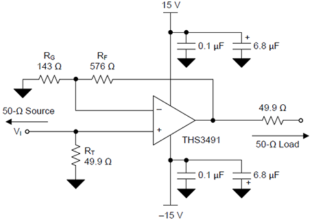
The traces below were obtained by installing the specified Rf and Rg resistors into the test bed above and measuring S21 from 300 kHz to 3 GHz on an HP 8753C VNA. Noise figures were measured at 10 MHz on an HP 8970B. All gain figures include the 6 dB loss in the series termination resistor.
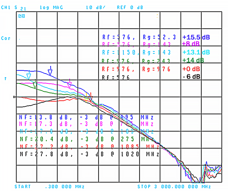
The measured noise figures seem to depend heavily on Rg, with less influence from Rf than one might expect from the standard opamp noise-gain equation. While likely an oversimplification, it's tempting to say that the noise figure of a non-inverting amplifier based on the THS3491 can be estimated as 10*log10(Rg) - 3 dB. Low-gain applications may benefit from smaller-than-recommended Rf and Rg values, trading off some HF peaking for better noise performance.
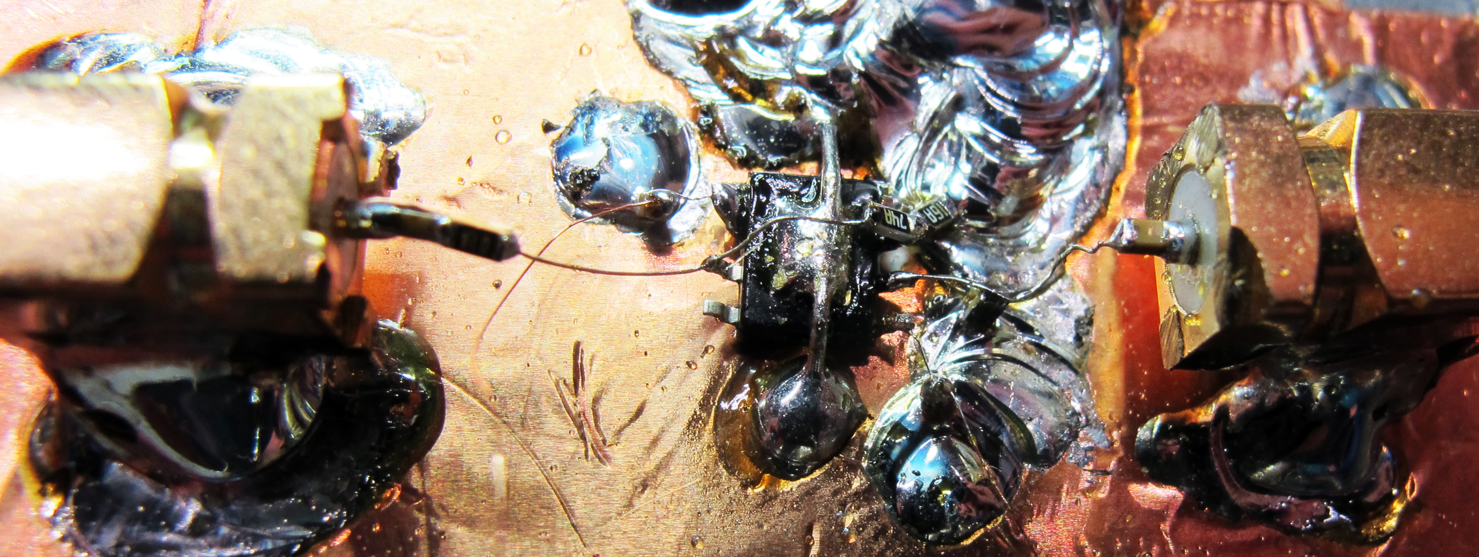
On that topic, it's worth noting that I used the 8-pin DDA package with the much-lower resistor values recommended by the data sheet for the RGT QFN package. It should be safe to do that in a PCB design if the top copper is opened up near the inverting input and the ground plane cut away beneath it. The only time I saw any significant peaking behavior was when running a unity-gain configuration with Rf=576 ohms and no Rg at all.
There is a bit of peaking near 1 GHz with Rf=976, Rg=976 that would probably go away with TI's recommended values of 2.1k, but that would simply have added some noise without improving the stability margin meaningfully.
A quick comparison of the residual phase noise obtained from the +8 dB amplifier configuration (Rf=576, Rg=143) above, relative to an LMH6702 amplifier configured for
similar gain:
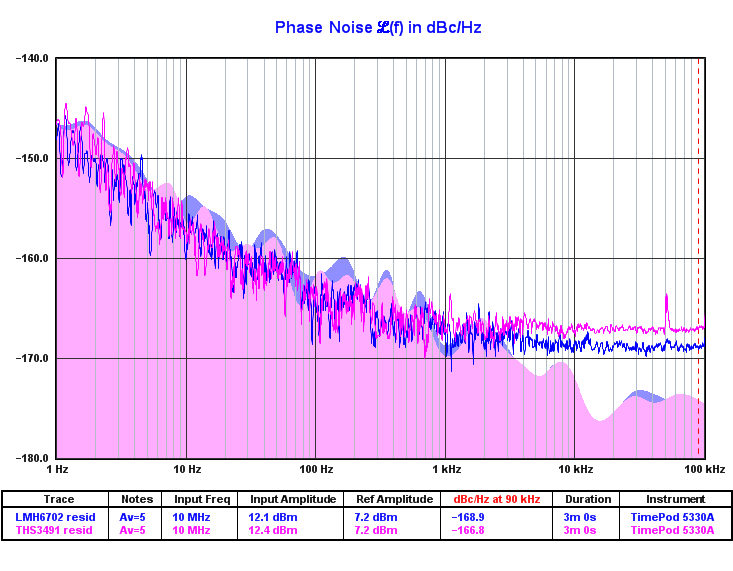
The THS3491's residual white PN of -166.8 dBc/Hz in this measurement, when added to its input power level of +7.2 dBm, works out to -159.6 dBm/Hz, or 17.4 dB above the thermal floor of -177 dBm/Hz. (The residual AM noise was essentially identical to the residual phase noise for the THS3491, hence the subtraction of 3 dB from the usual -174 dBm/Hz composite noise floor.) This agrees nicely with the noise figure reading of 17.3 dB from the HP 8970B in the previous plot.
The spur near 50 kHz in the THS3491 trace is an instrument artifact; both of these amplifiers are free of spurious responses within the 100 kHz analysis range. .TIM files may be downloaded here.
4-Jun-19: Photo and S21 plot of a THS3491-based amplifier deisgned to provide 25 dB of flat, stable gain at the four output channels of an AD9959 DDS:
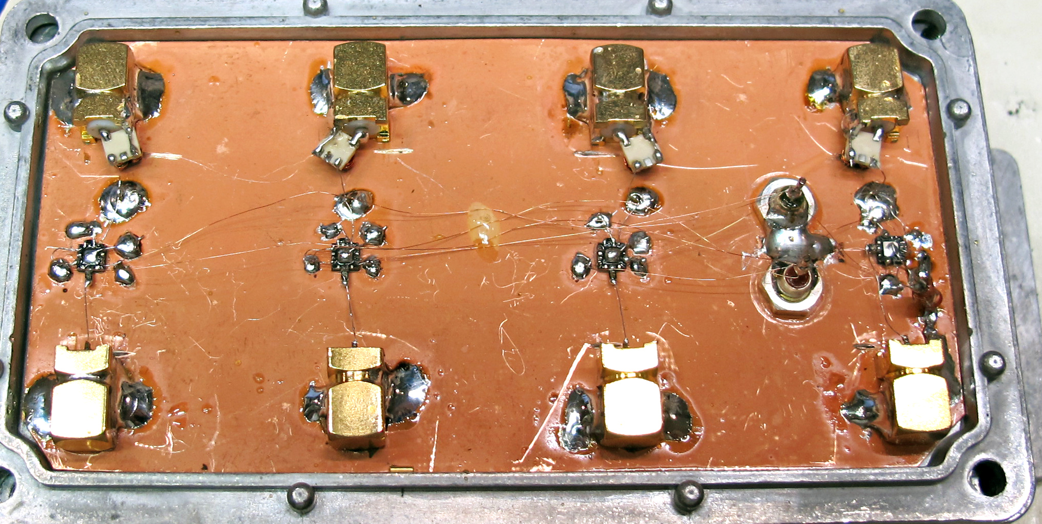
The amplifier under test is one of four identical channels utilizing the THS3491RGT with Rf=475 ohms and Rg=25.5 ohms. To improve noise performance, the noninverting input is driven by a TC4-1T+ transformer with Rt=200 ohms. Parasitics in the 300 MHz TC4-1T+ are responsible for the dip in gain near 1050 MHz.
Overall gain in this configuration is 25.5 dB, and is essentially flat from 100 kHz-200 MHz. Noise figure is close to 10.0 dB in the 10 MHz-200 MHz range. Maximum output power at 100 MHz is around +23 dBm. As with many other CFB amps, frequency-dependent nonlinear behavior including output power collapse occurs at higher levels, so the customary IP1dB and TOI specs are not meaningful with these parts.
Reverse isolation at 100 MHz is about 50 dB, somewhat worse than the 70 dB observed with lower-gain configurations with Rt=50 ohms. Isolation from the input of one channel to the output of an adjacent one is around 60 dB at 100 MHz, likely due to the ad-hoc power wiring.
Thermal considerations as well as lack of available drive power from the AD9959 limit the practical output power in this application to about +15 dBm. By the time the intended 200 MHz upper frequency limit is reached, the maximum achievable output power has fallen to roughly the same level.