Below are some measurements made with an experimental pair of cascaded regenerative dividers, which were constructed based on the topology described in Ferre-Pikal and Walls's 1997 IEEE paper Low PM Noise Regenerative Dividers (500KB).
Regenerative dividers offer several advantages over traditional digital frequency dividers, such as their exceptionally-low additive phase noise and their ability to work with clean sine-wave signals. The latter feature not only eliminates the usual need for edge-conditioning circuitry at the divider input, but can help with spur management at the system level as well. Commercial regenerative dividers are available from Wenzel Associates, but they are simple enough in principle to 'homebrew' in many cases.
The Ferre-Pikal paper argues for the importance of filtering the image frequency in the divider's feedback path. For example, the first divide-by-two circuit described below generates a 40-MHz output signal by mixing a sample of its own output with the incoming 80-MHz source. Overall loop gain is greater than one at 40 MHz, allowing the divider to start reliably.
The presence in the feedback path of the image frequency at 120 MHz, however, would contribute nothing but
additional noise to the regenerative conversion process, so it's removed with a low-pass filter. All regenerative
dividers need a phase-shift network of some type in the feedback path, but designs such as Ferre-Pikal's and
Wenzel's use low-pass filtering both before and after the gain stage to suppress the image response.
Topology and Schematics
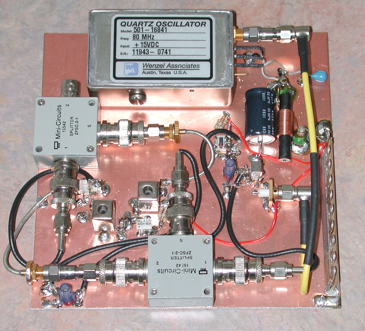
 The initial tests described here were conducted with two similar regenerative divider assemblies. Each assembly consists of
two cascaded divide-by-two stages, one to divide an 80-MHz input signal to 40 MHz and the other to divide this 40-MHz output to
20 MHz.
The initial tests described here were conducted with two similar regenerative divider assemblies. Each assembly consists of
two cascaded divide-by-two stages, one to divide an 80-MHz input signal to 40 MHz and the other to divide this 40-MHz output to
20 MHz.
This topology was chosen for two reasons: the first is that it will eventually allow me to upgrade the reference section
in my HP 8662A signal generator, and the second is that it places the divider output within the 30 MHz upper limit of
the TSC 5120A cross-correlating FFT phase noise analyzer that
Tom Van Baak of www.leapsecond.com fame
was kind enough to volunteer for testing.
The dividers' anticipated performance is better than the measurement floor of my HP 11729C carrier-noise test set, so it was necessary to resort to the
TSC 5120A to get the real story.
Initial Results
As of this writing, the LC filters in the divider feedback paths have been adjusted for stability but not optimized for phase-noise performance. Attenuators were used at the divider inputs to keep the ERA-5 MMIC amplifiers out of saturation, but no attempt was made to determine the effect of higher or lower input levels. Finally, the measurements were made with separate Wenzel ULN 80 MHz OCXOs driving each divider assembly, so we haven't taken advantage of the TSC-5120A's cross-correlation capabilities to measure the dividers' true residual noise floor.
For those reasons, perhaps, the observed performance falls short of the graphs in the Ferre-Pikal paper, specifically figure 4, where a broadband floor in the -176 dBc/Hz neighborhood is reported. Wenzel's divider specifications are also in the -172 to -175 dBc/Hz area. The 80-MHz OCXO specifications are more than good enough to allow the dividers to exhibit this level of performance, as is the TSC 5120A's measurement floor. So it's clear that there's some room for improvement in the dividers themselves.
The green and red traces compare each of the dividers individually with a 10 MHz Wenzel ULN OCXO with industry-leading phase-noise specs, while the yellow trace compares the same ULN10 oscillator with a similar 5-MHz part for reference purposes. If our dividers were performing as well as the ones in trace B of Ferre-Pikal's figure 4, both the green and red traces would be near the level of the yellow reference trace. Instead, they appear to be about 10 dB noisier than Ferre-Pikal's results.
These results are still quite impressive, considering the unoptimized configuration. The broadband floor is 8-10 dB better than any available digital divider can provide, and the noise levels conform very closely to those shown in figure 7 of Rubiola, Olivier, and Groslambert's Phase Noise in the Regenerative Frequency Dividers (IEEE Transactions on Instrumentation and Measurement, June 1992), in which the dividers under test were tuned for maximum output amplitude. Rubiola et al. suggest that a 10-dB improvement is possible with proper delay-line optimization.
Performance of the noisier of the two dividers at 20 MHz is about what you'd see from a "good" example of an HP 10811A OCXO at half the frequency. Further, head-to-head comparisons on the TSC 5120A and HP 11729C reveals that the HP 11729C's noise floor is better than I'd anticipated. (Note that neither the purple, the blue, nor the yellow traces have undergone subtraction of +3 dB to account for the RMS addition of two uncorrelated noise sources.)
One unanswered question is why the HP 11729C's trace shows a decrease in the broadband noise floor compared to the relatively-flat response on the TSC 5120A. The 11729C's trace should appear more noisy than the TSC 5120A's, not less. Numerous additional tests, including a true cross-correlation measurement of two similar dividers fed by a common source, need to be conducted in the future.
Acknowledgements
Thanks to Bruce Griffiths, Enrico Rubiola, and Magnus Danielson of the time-nuts list for advice and access to papers, and to Tom Van Baak for bench time on his TSC 5120A!