 This page describes a common-emitter HF amplifier with transformer feedback and active bias stabilization. This circuit, based on a design by Bruce Griffiths, provides a small amount of gain with about 40 dB of reverse
isolation at minimal component cost, along with exceptionally good residual phase-noise performance. These attributes make the circuit well-suited for use in buffer amplifier applications, where an internal signal needs to be routed externally
without adding noise.
This page describes a common-emitter HF amplifier with transformer feedback and active bias stabilization. This circuit, based on a design by Bruce Griffiths, provides a small amount of gain with about 40 dB of reverse
isolation at minimal component cost, along with exceptionally good residual phase-noise performance. These attributes make the circuit well-suited for use in buffer amplifier applications, where an internal signal needs to be routed externally
without adding noise.
The prototype characterized here was used to add a 10 MHz output jack to an HP 5061A cesium-beam standard. Many 5061As have
been upgraded in the field with the 10 MHz HP 10811-60109 OCXO from the 5061B model, but unlike "real" HP 5061Bs, the upgraded models didn't provide a 10 MHz
output at the front panel. A buffer amplifier is needed to keep from loading the 10811 excessively, to avoid injection-locking problems,
and to keep external signals out of the clock's control loop. Bruce's amplifier is a good candidate for this application.
Source Material and Circuit Description
HP 0105-6100 assembly schematic, used for 10811-60109 OCXO installation in HP 5061A, 5065A, 105B, and other instruments
Bruce's page on low-phase noise OCXO buffer amplifiers at ko4bb.com
Common-Base Transformer Feedback Norton Amplifiers by Dallas Lankford
New Norton-Rohde Feedback Amplifiers by Dallas Lankford
Transistor Amplifier with Impedance Matching Transformer, David E. Norton, US Patent 3,891,934, June 1975 (expired)
Clifton Laboratories' Z10040B Norton Noiseless Feedback Amplifier kit by Jack Smith, K8ZOA -- great source of app notes and design information
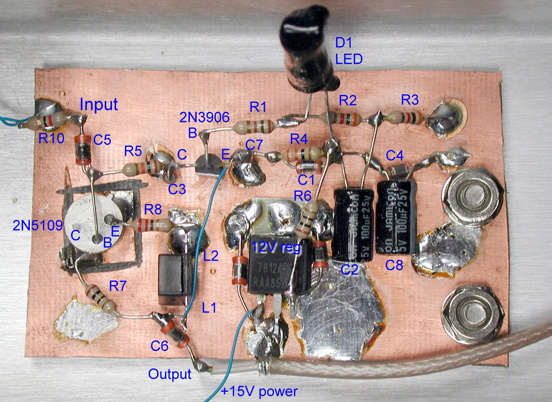
This particular amplifier circuit is a variation on David Norton's "noiseless feedback" topology from the early 1970s. In Bruce's circuit, the traditional common-base Norton scheme gives way to a common-emitter layout, with the transformer feedback element still present in the collector and emitter legs. DC bias stabilization is provided by a PNP stage with a well-filtered LED reference.
The LED specified by Bruce is a superbright part with a 2.0-volt typical forward drop, but I used a random part from the junk box with a forward drop closer to 1.7 volts. Gain is influenced chiefly by the transformer's turns ratio; I used a Mini-Circuits T13-1T transformer in my implementation. Transistor choices are equally uncritical, with a 2N5109 at Q1 and a 2N3906 at Q2 in my version of the circuit.
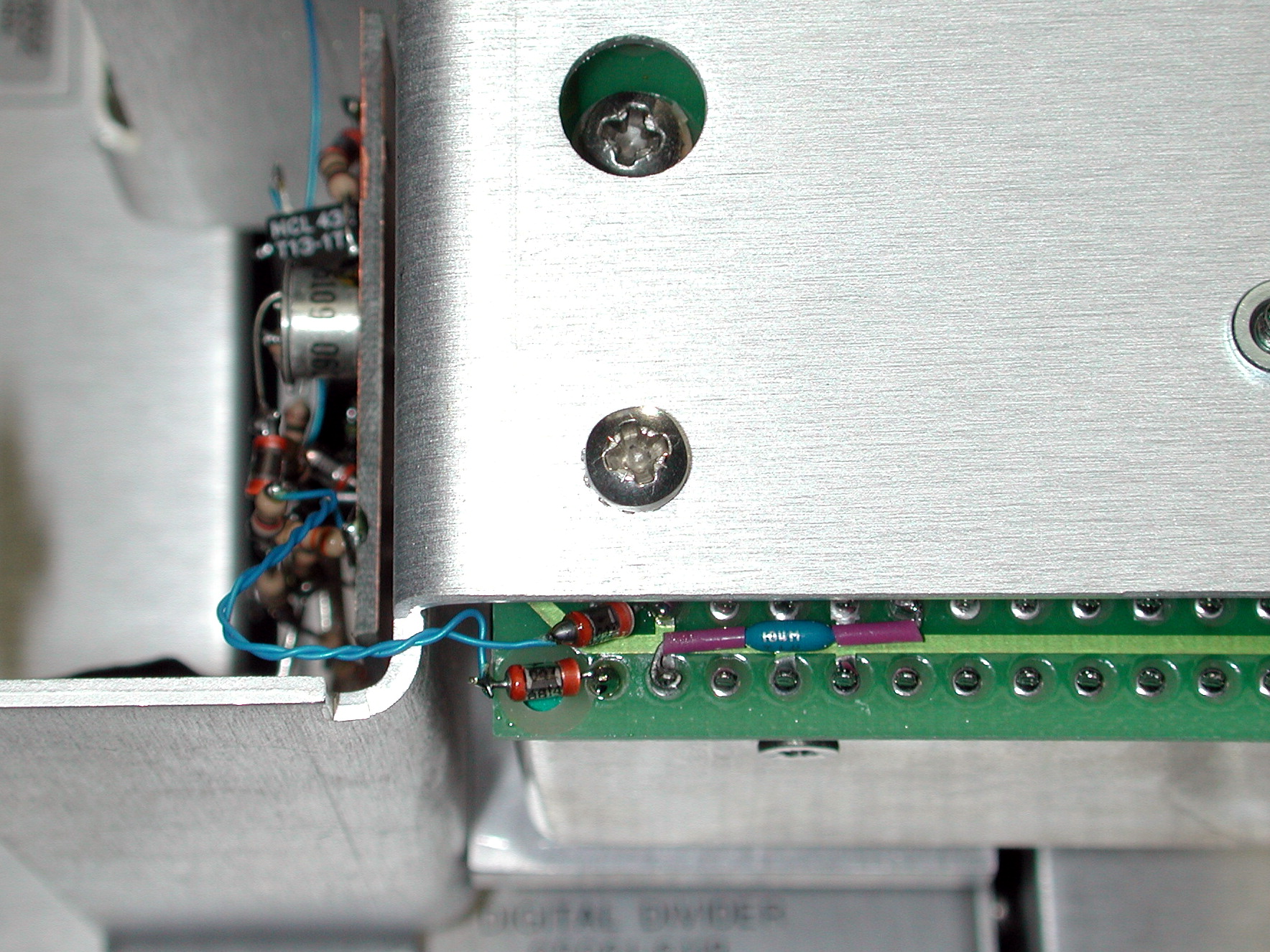
Input impedance is reasonably high, as typical of other common-emitter designs. Taking advantage of this, I used a 330-ohm resistor in place of R10 in the schematic above, with an 82-ohm resistor between the R10/C5 junction and the 10811's output pin (1, see photo below at left). The 10811 is otherwise loaded by 511 ohms in this circuit, and the additional 400 ohms presented by the buffer amplifier doesn't appreciably lower the amplitude available to the 5-MHz divider stage (see plot below).
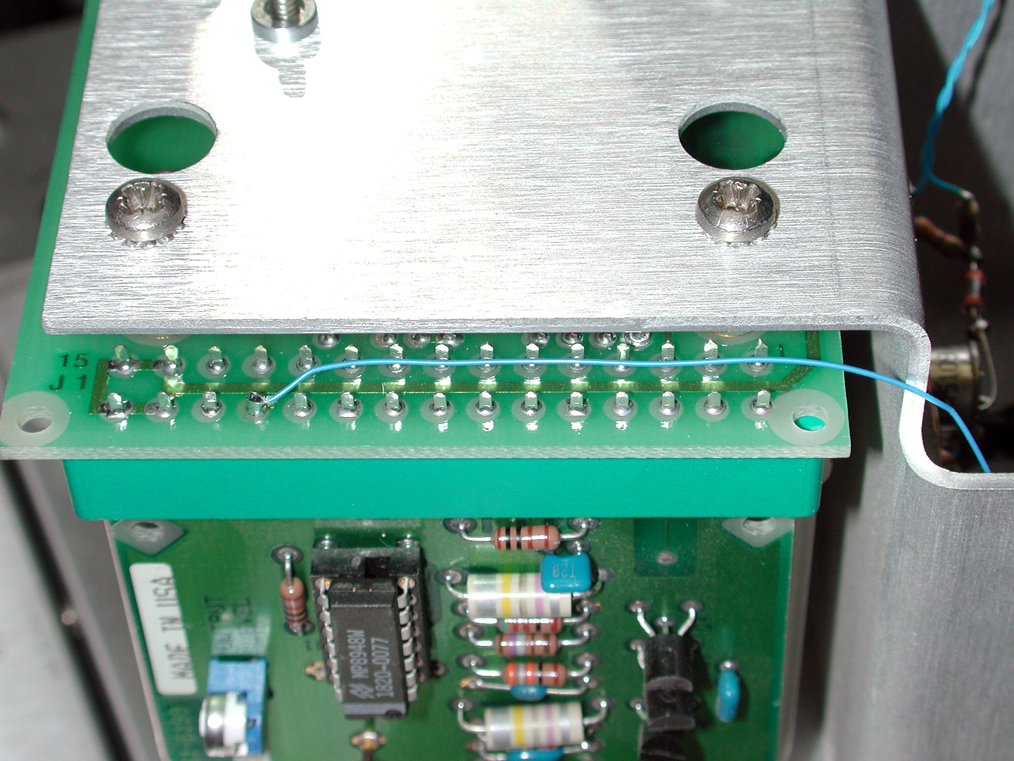
+12V is available from the A1A3 PC board, but I chose to use a separate 7812 regulator to avoid drawing too much current from the smaller 78L12 at U1. The 7812's input is
tied to the main +24V bus at A1A3 pin 12, visible in the photo (below, right).
Residual Phase Noise
At 5 MHz (left screenshot above), the additive phase noise imposed by the amplifier is very close to the HP 3048A's own measurement floor. Shown for comparison is a
more complex TNS grounded-base amplifier design and a simple MMIC amplifier constructed with a Mini-Circuits GALI-3. All of these amplifiers are good performers, capable
of amplifying the signal from a 10811-class OCXO without adding much phase noise. Only the CE Norton amp, however, offers a good compromise
between S12 and circuit complexity.
A similar test conducted at 10 MHz reveals that the Norton amplifier offers better performance than either of the other candidates. It's still very close
to the HP 3048A's own residual floor.
S-parameter Measurements
The plot above shows observed gain (S21) and reverse isolation (S12), with R10=51 ohms and the T13-1T transformer in place. The 2N5109 at Q1
offers good flatness through 100 MHz and beyond, although S12 begins to degrade beyond 10 MHz. This could be due to the rather sloppy layout used in my prototype,
and/or the characteristics of the Mini-Circuits transformer.
The plot above shows input and output VSWR, respectively, with R10=51 ohms.
Additional Measurements
This plot shows the measured effect of the buffer amplifier's input network (82 ohms from 10811 input to R10-C5 junction, R10 = 330 ohms) on the 10811's output signal as seen at U1A.
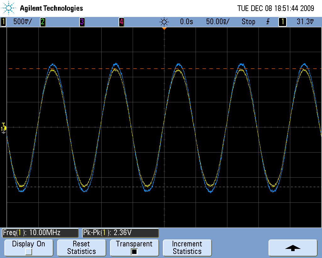
Above is the output spectrum from the 5061A's newly-added 10-MHz jack.
Additional notes and correspondence
November 8, 2020 Thanks to Taka Kamiya, KB4EMF/ex JF2DKG for his contribution of KiCad PCB files and Gerbers for the amplifier!
September 27, 2021 Andrey, UR5FFR has some curated notes on similar amplifier circuits on his Russian-language forum here (via Google Translate, alternate link here). Most of these are collected in the Amplifiers topic, but the rest of Andrey's forum is well worth surfing through.
October 19, 2021 Another dead-bug implementation of Bruce's amplifier can be seen below, comparable to the second schematic diagram on the page. This one is constructed with a mix of through-hole and surface-mount components. Q1 consists of two MMBT3904 transistors in parallel rather than the single 2N5109 used previously. The bases are tied together, but each transistor has its own emitter and collector resistors. A T9-1+ transformer and Kingbright AP1608SRCPRV LED were used in this version.
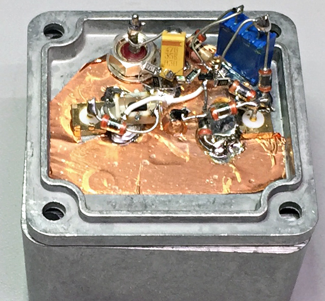
One additional modification is the use of a trimpot at R4 to adjust the bias, rather than a fixed 33-ohm resistor. Conveniently enough, the amplifier's bias current in milliamps is very close to the reciprocal of R4 in ohms, given that the difference between Q2's Vbe and the red LED's forward voltage drop is approximately 1.0 volts. The MMBT3904 pair will overheat if the original circuit is powered with the +12V source shown, but they work nicely with the bias dialed back to 25 mA (i.e., R4=39 ohms) and the supply voltage reduced to +6V.
Under these conditions, forward gain measured +6 dB at 10 MHz, with a 1-dB input compression point near +10 dBm. (The amplifier continues to work well at +5 volts, but there's not much headroom for bias stabilization at the 25 mA level.) The gain falls off smoothly with frequency, reaching +3 dB at 130 MHz. The noise figure as reported by the HP 8970B was 7.8 dB with the amplifier's 50-ohm input termination in place.
If you choose to try a similar approach, it'd be a good idea to replace the trimpot with a fixed resistor once you've determined a suitable class-A operating point for your transistor and supply voltage choices. Otherwise the trimpot may become noisy or intermittent over time due to the presence of DC current.
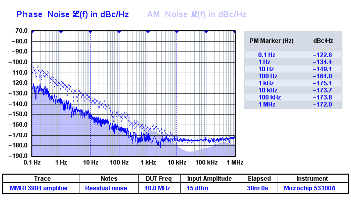
Residual phase noise performance is comparable to that of the 2N5109 amplifier, in which the instrument floor dominated the measurement. Few 10 MHz oscillators will be significantly degraded by this amplifier, and only then at offsets beyond 100 Hz.