LCOPY.EXE is a simple Windows console application that can save significant amounts of time when multiple identical sections of a schematic
need to be laid out identically on the PC board. It will automatically place components at offsets that mimic the relative positions
of similar components already on the board.
LCOPY can be downloaded here. This zipfile includes .cpp sources and a makefile compatible with Visual C++. To rebuild LCOPY.EXE, you can use either the Enterprise or free Community edition of the Visual Studio package, configured to enable command-line compilation.
LCOPY is compatible with XML schematic and board files written by EAGLE V6 and later versions. In addition to its ability to help with repetitive layout tasks, it's hoped that LCOPY will also serve as a useful example of EAGLE XML file access in C++. The current version of LCOPY can duplicate placed components, silkscreen names, routed traces, polygons, and vias. Any patches and improvements are (very!) welcome.
Usage
LCOPY should be launched from a Windows command prompt (aka a "DOS box.") Running lcopy /? will display the following usage notes:
____________________________________________________________________

EAGLE LCOPY version 2.01 of Dec 18 2018 by John Miles, KE5FX

This program places components from a target schematic area at a
specified offset from the positions of corresponding components
in a reference schematic area
____________________________________________________________________

Usage: lcopy

Arguments:
        /sch:        Name of EAGLE .sch input file
        /brd:        Name of EAGLE .brd input file
        /out:        Name of EAGLE .brd output file
        /ref:        Area in schematic of already-placed components
     /target:        Area in schematic of components to be placed
       /vias:        Create copies of vias in reference area
      /wires:        Create copies of routed wires in reference area
   /polygons:        Create copies of polygons in reference area
       /area:        Specify optional explicit reference boundaries

Example:
     lcopy /sch:foo.sch /brd:foo.brd /out:bar.brd /ref:1,a1,a2 /target:1,b1,b2

Notes and assumptions:

   - Reported coordinates are in millimeters (regardless of grid setting)

   - Schematic areas are specified as , where the
     optional tag pair refers to two text objects placed at opposite
     corners of the desired area of the schematic sheet in layer 97 (Info).
     If no tags are specified, all parts on the schematic sheet are processed.

   - Schematic sheet #s are 1-based

   - Components in schematics are all in quadrant 0 (i.e., positive X and Y)

   - The first target component with a positive X coordinate on the board
     is left in place as a 'seed.' Its X,Y offset relative to its counterpart
     on the reference sheet is applied to all other target components.

   - Both mirrored (bottom) and unmirrored (top) components are supported,
     along with their silkscreen names and values, if any

   - Use /area to duplicate objects such as ground vias appearing outside the
     reference set

   - Always issue a RATSNEST command as soon as you load the modified .brd
     file in EAGLE, in order to recalculate the airwires for the relocated
     components

   - Back up your .brd file first!
This software is provided 'as-is', without any express or implied warranty. In no event will the authors be held liable for any damages arising from the use of this software.
Permission is granted to anyone to use this software for any purpose, including commercial applications, and to alter it and redistribute it freely, subject to the following restrictions:
1. The origin of this software must not be misrepresented; you must not claim that you wrote the original software. If you use this software in a product, an acknowledgment in the product documentation would be appreciated but is not required.
2. Altered source versions must be plainly marked as such, and must not be misrepresented as being the original software.
3. This notice may not be removed or altered from any source distribution.
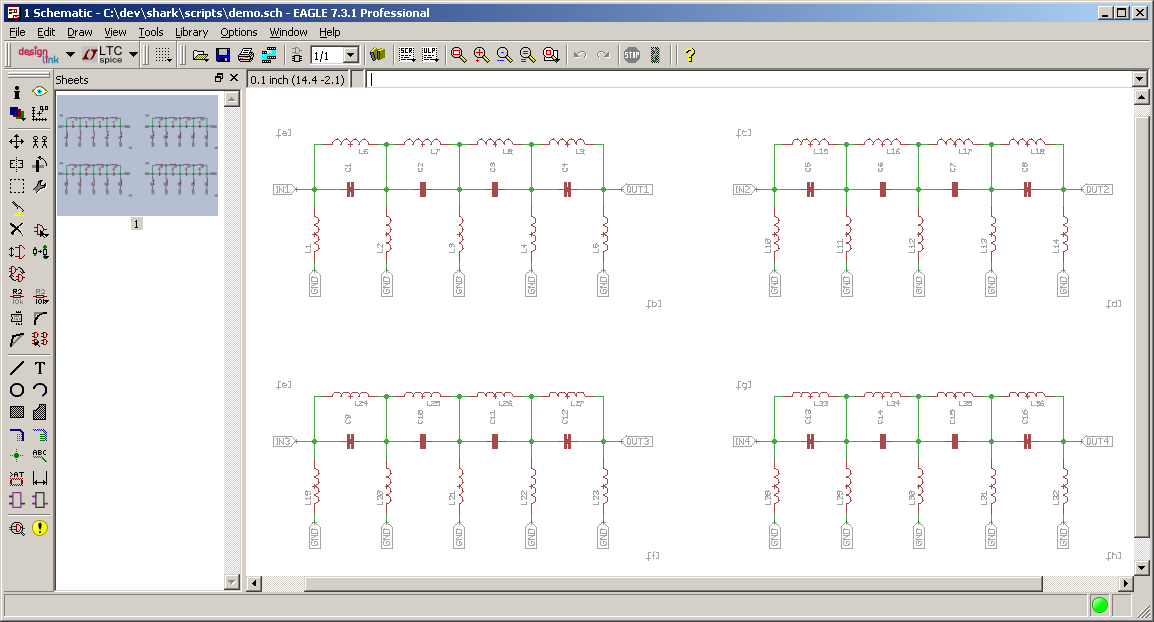
Note the addition of the [a]...[h] text tags in layer 97 (Info). In the example below, LCOPY will use the tags to identify the subset of components
to be used as a placement reference ([a][b]) for the other three copies ([c][d], [e][f], and [g][h]).
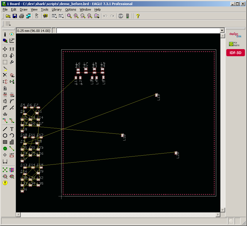
Above, the components from the [a][b] section have been pre-placed by the user, along with one 'anchor' component from the [c][d], [e][f], and [g][h] regions to be copied. For each component in the [a][b] region, LCOPY will identify the closest component in the other three regions and move it to a similar offset relative to that region's anchor component.
The following three LCOPY commands will perform the necessary component placements, saving the final result to
demo_after.brd. User commands are highlighed in red.
c:\test\>lcopy /sch:demo.sch /brd:demo_before.brd /out:demo1.brd /ref:1,[a],[b] /target:1,[c],[d] /wires Area on sheet 1 specified by [a],[b]: (154.94, -20.32) to (259.08, 27.94) Area on sheet 1 specified by [c],[d]: (284.48, -20.32) to (388.62, 27.94) Ref Target Dist Bx By ---------------------------------------------------------- L1 L10 0.00 8.00 65.50 (Anchor) L2 L11 0.00 10.50 65.50 L3 L12 0.00 17.00 65.50 L4 L13 0.00 19.50 65.50 L5 L14 0.00 23.25 65.75 C1 C5 0.00 9.25 68.25 C2 C6 0.00 13.50 68.25 C3 C7 0.00 18.25 68.25 C4 C8 0.00 22.75 68.25 L6 L15 0.00 9.25 70.00 L7 L16 0.00 13.50 70.25 L8 L17 0.00 18.25 70.25 L9 L18 0.00 22.75 70.25 Anchor component: L10 at (33.61, 33.67), offset from L1 = (25.61, -31.83) Moving L11 from (-13.48, 45.86) to (36.11, 33.67) Moving L12 from (-21.61, 42.33) to (42.61, 33.67) Moving L13 from (-17.16, 42.33) to (45.11, 33.67) Moving L14 from (-12.72, 42.33) to (48.86, 33.92) Moving C5 from (-20.08, 49.04) to (34.86, 36.42) Moving C6 from (-16.40, 49.04) to (39.11, 36.42) Moving C7 from (-12.72, 49.04) to (43.86, 36.42) Moving C8 from (-20.08, 45.51) to (48.36, 36.42) Moving L15 from (-21.61, 39.16) to (34.86, 38.17) Moving L16 from (-17.16, 39.16) to (39.11, 38.42) Moving L17 from (-12.72, 39.16) to (43.86, 38.42) Moving L18 from (-21.61, 35.98) to (48.36, 38.42) Done, 13 component(s) placed
c:\test\>lcopy /sch:demo.sch /brd:demo1.brd /out:demo2.brd /ref:1,[a],[b] /target:1,[e],[f] /wires
Area on sheet 1 specified by [a],[b]: (154.94, -20.32) to (259.08, 27.94) Area on sheet 1 specified by [e],[f]: (154.94, -91.44) to (259.08, -43.18) Ref Target Dist Bx By ---------------------------------------------------------- L1 L19 0.00 8.00 65.50 (Anchor) L2 L20 0.00 10.50 65.50 L3 L21 0.00 17.00 65.50 L4 L22 0.00 19.50 65.50 L5 L23 0.00 23.25 65.75 C1 C9 0.00 9.25 68.25 C2 C10 0.00 13.50 68.25 C3 C11 0.00 18.25 68.25 C4 C12 0.00 22.75 68.25 L6 L24 0.00 9.25 70.00 L7 L25 0.00 13.50 70.25 L8 L26 0.00 18.25 70.25 L9 L27 0.00 22.75 70.25 Anchor component: L19 at (52.53, 55.92), offset from L1 = (44.53, -9.58) Moving L20 from (-13.48, 29.28) to (55.03, 55.92) Moving L21 from (-21.61, 25.75) to (61.53, 55.92) Moving L22 from (-17.16, 25.75) to (64.03, 55.92) Moving L23 from (-12.72, 25.75) to (67.78, 56.17) Moving C9 from (-20.08, 28.92) to (53.78, 58.67) Moving C10 from (-20.08, 32.45) to (58.03, 58.67) Moving C11 from (-15.64, 32.45) to (62.78, 58.67) Moving C12 from (-11.19, 32.45) to (67.28, 58.67) Moving L24 from (-21.61, 22.57) to (53.78, 60.42) Moving L25 from (-17.16, 22.57) to (58.03, 60.67) Moving L26 from (-12.72, 22.57) to (62.78, 60.67) Moving L27 from (-21.61, 19.40) to (67.28, 60.67) Done, 13 component(s) placed
c:\test\>lcopy /sch:demo.sch /brd:demo2.brd /out:demo_after.brd /ref:1,[a],[b] /target:1,[g],[h] /wires
Area on sheet 1 specified by [a],[b]: (154.94, -20.32) to (259.08, 27.94) Area on sheet 1 specified by [g],[h]: (284.48, -91.44) to (388.62, -43.18) Ref Target Dist Bx By ---------------------------------------------------------- L1 L28 0.00 8.00 65.50 (Anchor) L2 L29 0.00 10.50 65.50 L3 L30 0.00 17.00 65.50 L4 L31 0.00 19.50 65.50 L5 L32 0.00 23.25 65.75 C1 C13 0.00 9.25 68.25 C2 C14 0.00 13.50 68.25 C3 C15 0.00 18.25 68.25 C4 C16 0.00 22.75 68.25 L6 L33 0.00 9.25 70.00 L7 L34 0.00 13.50 70.25 L8 L35 0.00 18.25 70.25 L9 L36 0.00 22.75 70.25 Anchor component: L28 at (63.19, 23.91), offset from L1 = (55.19, -41.59) Moving L29 from (-12.72, 12.69) to (65.69, 23.91) Moving L30 from (-21.61, 9.16) to (72.19, 23.91) Moving L31 from (-17.16, 9.16) to (74.69, 23.91) Moving L32 from (-12.72, 9.16) to (78.44, 24.16) Moving C13 from (-20.08, 15.87) to (64.44, 26.66) Moving C14 from (-15.64, 15.87) to (68.69, 26.66) Moving C15 from (-11.19, 15.87) to (73.44, 26.66) Moving C16 from (-20.08, 12.34) to (77.94, 26.66) Moving L33 from (-21.61, 5.99) to (64.44, 28.41) Moving L34 from (-17.16, 5.99) to (68.69, 28.66) Moving L35 from (-12.72, 5.99) to (73.44, 28.66) Moving L36 from (-21.61, 2.81) to (77.94, 28.66) Done, 13 component(s) placed
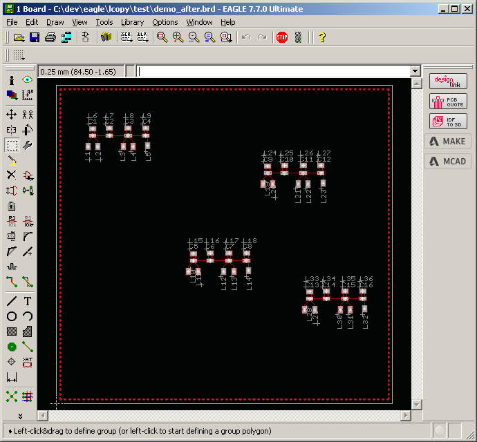
Loading demo_after.brd into EAGLE, followed by a RATSNEST command to recalculate the airwires, will yield the above result.