Below are some measurements on cesium-beam tube 05062-60500 serial 1936A01035. This is the physics package from an HP 5062C atomic clock, a 1970s-era model designed for high reliability and serviceability in airborne/maritime applications.
Obtained as usual from an eBay seller, the tube appeared to have experienced a long shelf life, as the 300 uA ion-pump supply immediately went into current limiting when the hot-wire ionizer was powered up. At the suggestion of Corby Dawson on the time-nuts mailing list, I applied a 5-mA 3KV supply to the ion pump to force it to scavenge the contents of the vacuum envelope that were released by the ionizer filament.
It took several alternating activations of the 5-mA supply and hot-wire ionizer current before the ion-pump current fell below the 300-uA supply's limit and remained there with the ionizer filament powered up. After a few more hours of operation, the ion-pump current reached its 10-uA specification limit with all supplies active.
")
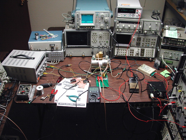
Test Setup and Initial Results
Getting the cesium-beam tube up and running took nearly every power supply on hand. Bertan 605C-200P and PMT-50CN-1 high-voltage supplies were used to drive the ion pump and electron multiplier at +2600V and -1975V, respectively. A 1-volt, 1-amp supply was applied to the hot-wire ionizer, elevated to 13.9V in accordance with the mass spectrometer specification marked on the tube. The cesium oven was brought up to temperature slowly with a 0-50V bench supply, beginning with 25 volts at 1 amp and levelling off after 5-10 minutes at almost exactly 7.000 volts with a reading of 190-200 ohms on the oven thermistor. Finally, a 5-volt supply drove the C-field coil through a 220-ohm resistor.
RF excitation was provided by an HP 8672A signal generator at its maximum output, measured at the tube connector, of +9.7 dBm. I believe the tube would prefer to have some additional drive power, since the output signal amplitude was still increasing monotonically up to the 8672A's limit.
The 8672A was set to 9192.632 MHz and driven from an adjustable HP 10811-60168 OCXO, allowing the actual output frequency to be steered toward the tube's rated frequency of 9,192,631,774.3 Hz. To accommodate various correction factors, this frequency is 4.3 Hz higher than the cesium hyperfine-transition frequency at 0 Kelvin that literally defines the "second."
The EFC input of the 10811-60168 OCXO was modulated with a 0.025 Hz sinewave from an HP 3325B function generator, resulting in a slow, repetitive sweep covering approximately 6 kHz either side of the center frequency.
Pass/Fail...?
This basic signal/noise measurement suggests that the tube is good, noting that without the beam-current amplifier circuit (A16U1 from the 5062C, reproduced almost verbatim for this test), the cesium resonance envelope amplitude is only about 5 mV pk-pk into a 10-megohm oscilloscope probe. This suggests that the peak-to-peak beam current is on the order of 0.5 nA. A16U1 turns input current into output voltage with a gain of 1E+8, so the 0.5 nA figure corresponds well to the 45-mV pk-pk amplitude in the plots above.
The minimum-specification limit given on page 4-37 of the HP 5062C manual is Ip >= 5 nA. This does not appear to refer to the envelope's peak-to-peak amplitude, though, but rather the peak beam current above ground potential, measured at the beam-current test point at A16U1's output with the electron multiplier at its maximum voltage of -2.7 kV.
In the noise test plot above, Ip is 155 mV * 1E-8 = 1.55 nA with the electron multiplier at -1975 V. Increasing the EM potential to -2.7 kV
yielded an Ip of 4.5 nA, much closer to specification:
Chances are good that the tube will meet its specs without difficulty once the other variables such as RF drive level are
optimized.