 Turning down the intensity control on a CRT-based instrument doesn't do much to extend the life of its CRT.
It'll
prevent phosphor burn-in, of course... but cathode emission loss can actually be accelerated by running with the
intensity turned all the way down.
Turning down the intensity control on a CRT-based instrument doesn't do much to extend the life of its CRT.
It'll
prevent phosphor burn-in, of course... but cathode emission loss can actually be accelerated by running with the
intensity turned all the way down.
Some HP spectrum analyzers, like the 8566-8568 models, support a handy keyboard shortcut that kills the entire CRT power supply -- filament, grid, and HV. This function, assigned to the shift-g and shift-h keys on the HP 85662A display, stops all CRT aging mechanisms in their tracks. It's useful during lengthy automated measurements that don't require the operator to view the display. I wanted a similar feature for my Tektronix 494AP portable model.
I often use my 494AP for unattended monitoring on 2.4 GHz and other bands. It's equipped with a desirable and relatively-uncommon reduced-scan CRT (option 43). The CRT is in mint condition... and if I could turn the CRT power supply on and off under either front-panel or GPIB control, it would stay that way!
One solution appears in the photos and schematics here. Tektronix 490- and 2750-series analyzers have a little-used READOUT button
on the front panel that disables the onscreen text display of center frequency,
reference level, and other parameters. This modification describes how to
use the READOUT button to turn the entire CRT power supply on and off, just like the HP 85662A.
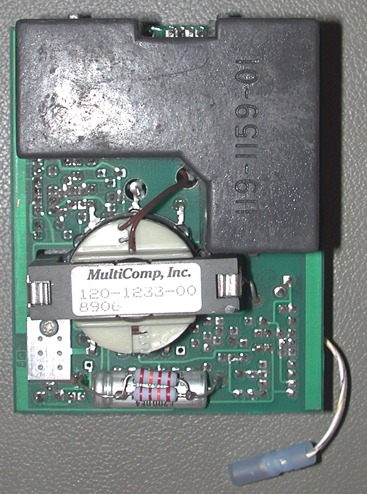
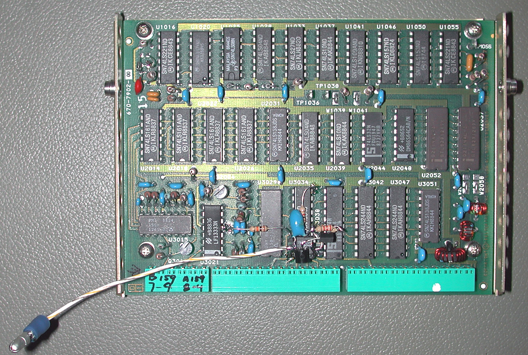 At right is the readout control board from the Tektronix 494AP with the newly-added components
shown in the schematic below. The modification is easy to make, and easy to reverse if desired.
At right is the readout control board from the Tektronix 494AP with the newly-added components
shown in the schematic below. The modification is easy to make, and easy to reverse if desired.
A pair of 2N3906 PNP transistors and a 4N28 optoisolator connect the readout-status signal from the analyzer's internal bus with a node on the high-voltage power supply board that is ordinarily used as an undervoltage safety shutdown. When the user turns the READOUT button off, the TTL READOUT_ON line goes low, allowing C1 to charge through R2 and R1. After a few hundred milliseconds, the voltage across C1 reaches two Vbe diode drops (about 1.2V) and the Darlington pair turns the optocoupler on, applying a negative bias to the HV shutdown node to stop the oscillator.
It's fairly common for the 494AP firmware to blank the readout for a few hundred milliseconds at various times, such as when entering the built-in HELP mode or calling up a menu. A relatively-high value at R1 helps the circuit ignore these momentary glitches on the readout-control line, while D1 ensures that C1 discharges quickly when the readout is turned back on.
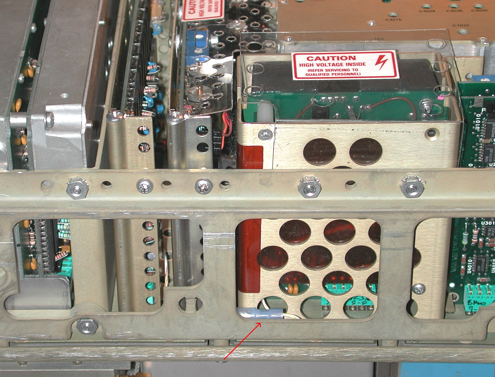
A single wire with a quick-disconnect plug, visible in the photo at the top of the page, runs between the readout and HV power-supply boards.
Other 490- and 2750-series analyzers use very similar hardware, so it shouldn't be hard to apply this modification to instruments dating back to the earliest 492s.
 Shown here are the necessary changes to the CRT power supply board.
As noted in the schematic below, a 10K, 2-watt resistor needs to be added across C2084, an 8-uF 200V aluminum electrolytic filter capacitor. Without it, the unregulated 100-volt power supply soars to 150 volts when Q1073 is biased into cutoff, causing a power-supply regulation error message.
At right, the cathode of CR4071 offers a good connection point for the wire leading back to pin 5 of the
optoisolator on the readout board.
Below, the green trace shows the (inverted) voltage at U1's emitter, in response to turn-off and turn-on commands from the READOUT button, respectively. It's possible that analyzers with different firmware versions may need larger R1/C1 time constants to avoid unwanted screen flicker in some circumstances as noted above. The 330K / 22 uF values used here should be a good starting point.
 Finally, a working SwitcherCAD III / LTSpice simulation of the circuit may be downloaded
by clicking on either image.
Finally, a working SwitcherCAD III / LTSpice simulation of the circuit may be downloaded
by clicking on either image.
Considering the usual variations in transistor beta and the real-world sensitivity of the 4N28 optoisolator, the accuracy of the simulation isn't bad at all.