 This page recounts a 45-day experiment in restoring or "rejuvenating" the cathode-ray tube in an HP 85662A spectrum
analyzer display unit. These are commonly found in various surplus electronics venues including eBay, either by themselves or as part of an HP 8566, 8567, or 8568
analyzer outfit. The HP 85662A was arguably one of the finest small CRT displays produced by Hewlett-Packard
or any other T&M equipment manufacturer, but like any other CRT-based device, they aren't getting better with age.
This page recounts a 45-day experiment in restoring or "rejuvenating" the cathode-ray tube in an HP 85662A spectrum
analyzer display unit. These are commonly found in various surplus electronics venues including eBay, either by themselves or as part of an HP 8566, 8567, or 8568
analyzer outfit. The HP 85662A was arguably one of the finest small CRT displays produced by Hewlett-Packard
or any other T&M equipment manufacturer, but like any other CRT-based device, they aren't getting better with age.
I've owned several of these display units; this example was by far the weakest. It was purchased in one of those increasingly-common eBay auctions in which the seller used a stock photograph of one item to sell a different example in much rougher condition. Although the CRT phosphor was undamaged, the tube was unusable due to a phenomenon known variously as "cathode interface" or "cathode poisoning."
 Exactly what "cathode poisoning" is seems to depend on who you ask. But
most sources refer to the development of an insulating layer composed of oxides or other ions that interferes with the cathode's
ability to emit its electron beam. The insulating layer acts as an unwanted electrical capacitance in series with the cathode, and may also introduce thermal lag
effects. Overall intensity is reduced markedly, and -- at least in these HP CRTs -- both intensity and focus become very dependent on
the frequency of the cathode drive signal, i.e., the rate at which the beam's intensity is varied.
Exactly what "cathode poisoning" is seems to depend on who you ask. But
most sources refer to the development of an insulating layer composed of oxides or other ions that interferes with the cathode's
ability to emit its electron beam. The insulating layer acts as an unwanted electrical capacitance in series with the cathode, and may also introduce thermal lag
effects. Overall intensity is reduced markedly, and -- at least in these HP CRTs -- both intensity and focus become very dependent on
the frequency of the cathode drive signal, i.e., the rate at which the beam's intensity is varied.
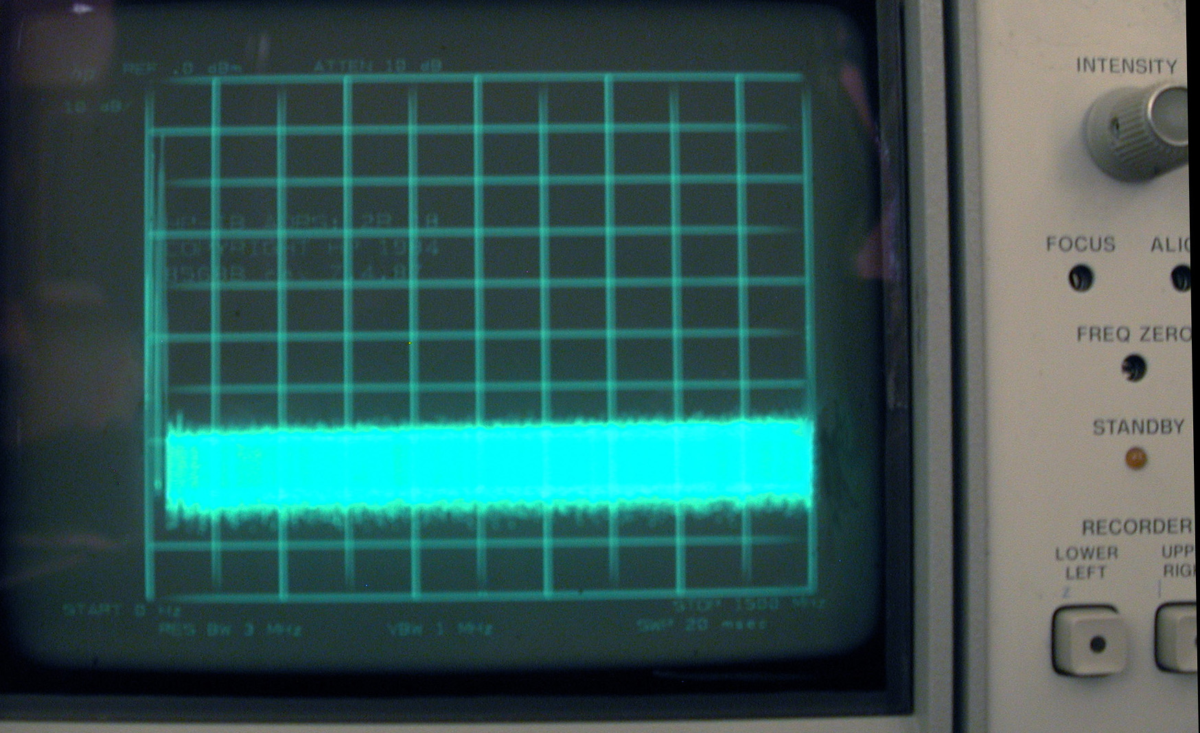
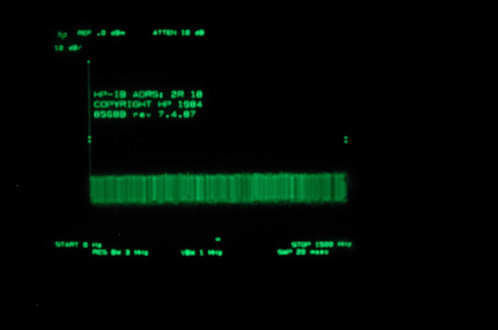
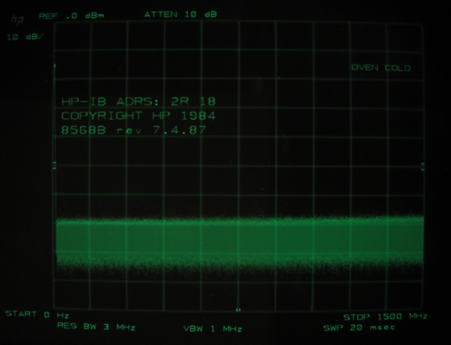
In HP displays of this vintage, it eventually becomes impossible to focus both the long graticule vectors and the shorter text/trace vectors at the same time. The display circuitry renders short vectors approximately 5x as quickly as long ones, leading to time-dependent effects that are clearly observable in the "before" photograph (upper left). Z-axis drive is determined by the line length as well; shorter and faster vectors need more grid current.
In the photo, the long graticule lines are badly defocused, and the beginning of each stroke drawn with low grid current is invisible. The text characters are nearly as dim. The trace itself is relatively bright, but not as well-focused as the characters. These symptoms are all very typical of HP CRTs with end-stage cathode poisoning.
Surprisingly, I was not all that unhappy with this purchase. The price was reasonable, the rest of the HP 8568B system was OK... and I had a good excuse to try out some ideas regarding homebrew "emulation" of an expensive Sencore CRT restoration rig.
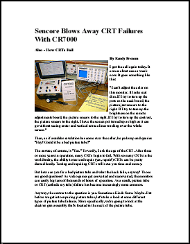 At some point in my Internet travels, I'd come across a .PDF reprint of Randy Fromm's article, "Sencore Blows Away CRT Failures with CR7000".
Appearing in Play Meter, a trade journal
aimed at arcade-game operators, Randy's article on a new Sencore CRT restorer
was not meant as a lifeline to owners of mostly-dead HP CRTs. Still, Randy's explanation of CRT failure modes had a
ring of general applicability to them. The details he revealed about the restoration procedures and grid-current levels used by Sencore's device were enough to
inspire informed experimentation, with a reasonable chance that the tube would survive.
At some point in my Internet travels, I'd come across a .PDF reprint of Randy Fromm's article, "Sencore Blows Away CRT Failures with CR7000".
Appearing in Play Meter, a trade journal
aimed at arcade-game operators, Randy's article on a new Sencore CRT restorer
was not meant as a lifeline to owners of mostly-dead HP CRTs. Still, Randy's explanation of CRT failure modes had a
ring of general applicability to them. The details he revealed about the restoration procedures and grid-current levels used by Sencore's device were enough to
inspire informed experimentation, with a reasonable chance that the tube would survive.
I won't recount the contents of the article in detail here, but I'd encourage you to check it out for yourself, especially if you intend to perform a similar experiment. In a nutshell, the Sencore restorer works by "zapping" the tube, applying one or more brief pulses of current between the cathode and control grid that are substantially in excess of what the tube normally sees. Higher-than-usual filament voltage is often applied during this process. The idea is to heat the cathode enough to break through any insulating layers, forming or exposing a new emissive surface. If you're careful (and, perhaps, lucky), you won't "strip" the cathode, melt the grid, or otherwise hose the tube for good.
The nice thing about this particular eBay deal was the way it left me with literally nothing to lose. The tube was
unusable as delivered. So the possibility that the restoration process would have no effect, regress at an extreme rate,
or make the tube look even worse was not a concern.
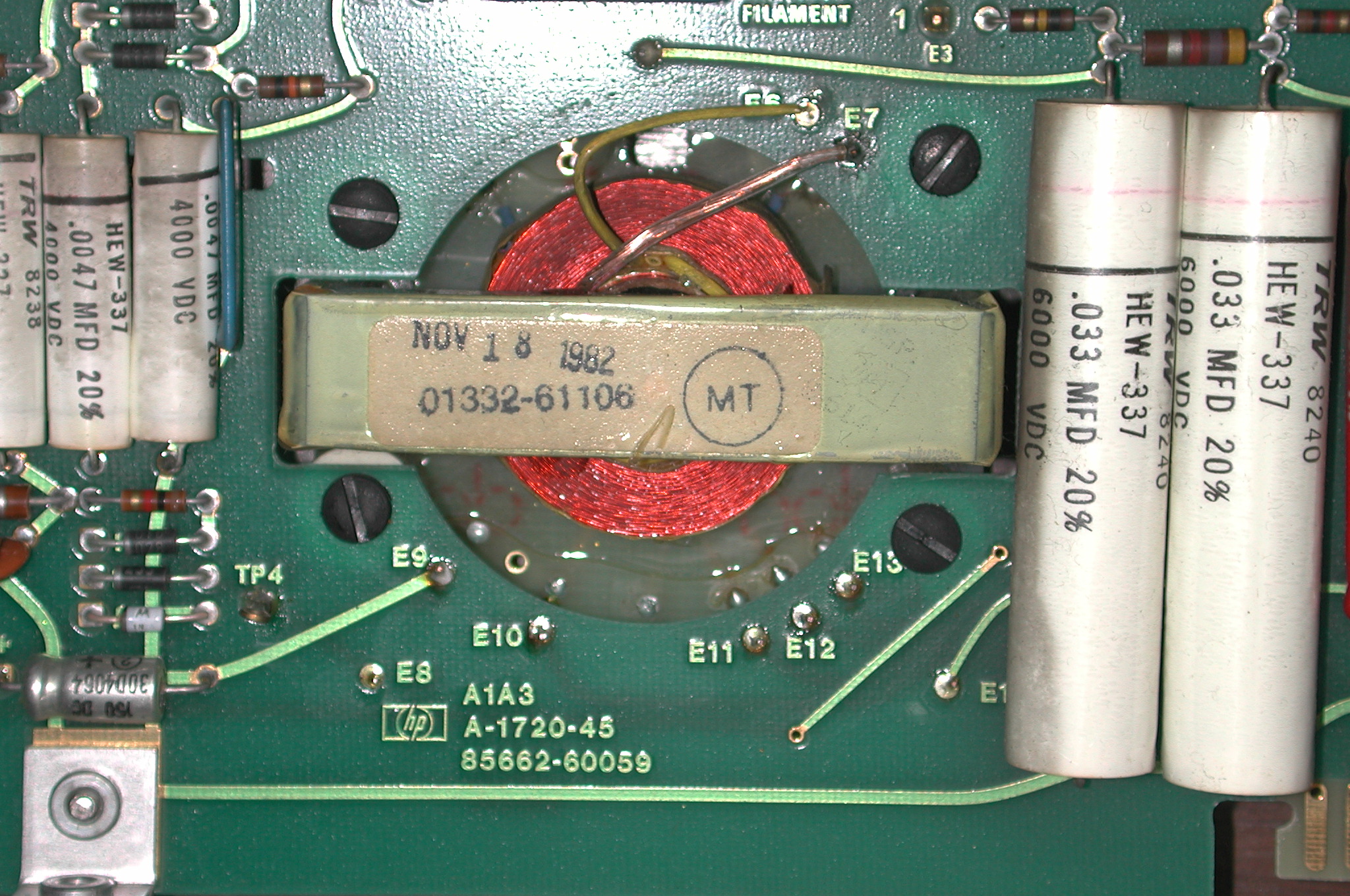
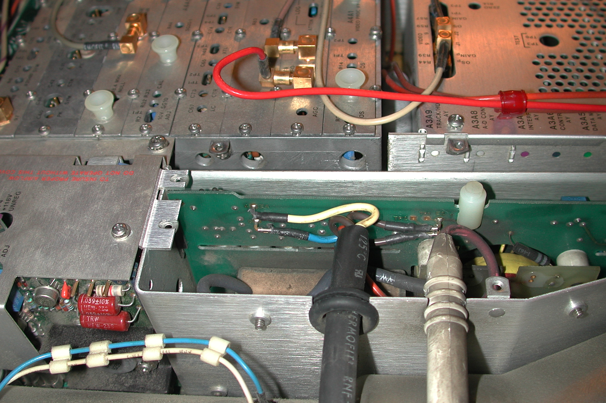 Fortunately, the HP 85662A's CRT connections
are easily accessible near the top of the high-voltage cage. In the photo at right, the brown wires lead to the filament; the yellow wire leads to the cathode;
and the blue wire leads to the control grid (G1). It was easy to disconnect and reconnect them for the test without removing much
hardware.
Fortunately, the HP 85662A's CRT connections
are easily accessible near the top of the high-voltage cage. In the photo at right, the brown wires lead to the filament; the yellow wire leads to the cathode;
and the blue wire leads to the control grid (G1). It was easy to disconnect and reconnect them for the test without removing much
hardware.
If you attempt to restore an 85662A CRT, be sure you've disconnected the AC line and all other cables from the HP 85662A before working inside the HV cage. Don't even open the cage until you've discharged the CRT's HV anode connector to the chassis. You may survive a 12,000-volt discharge from the CRT through the HV board, but various components throughout the 85662A won't. (Don't ask me how I know.)
I began the experiment by using a DC bench supply to run the CRT heater at 6.5 VDC, about 50% more than its normal 4.45V RMS specification. My grid-current source was rudimentary compared to the multi-kilobuck Sencore... a Variac and a voltage doubler with a 600-ohm series resistor made a workable, if somewhat hazardous, current-limited DC supply.
My initial application of grid current was limited to three manually-controlled "ramps" terminating at about 40 mA, each lasting about three seconds. The heater had been left running for approximately one minute at this point.
It was easy to visualize a change in the nature of the cathode surface by watching the grid current on a DMM. At first, the tube refused to draw more than a mA or so of grid current, until the grid voltage exceeded about 100 volts. The grid current spiked upwards at that point. This "breakthrough" effect was observed on the first ramp, and the relationship between grid current and voltage was much more linear on subsequent ramps.
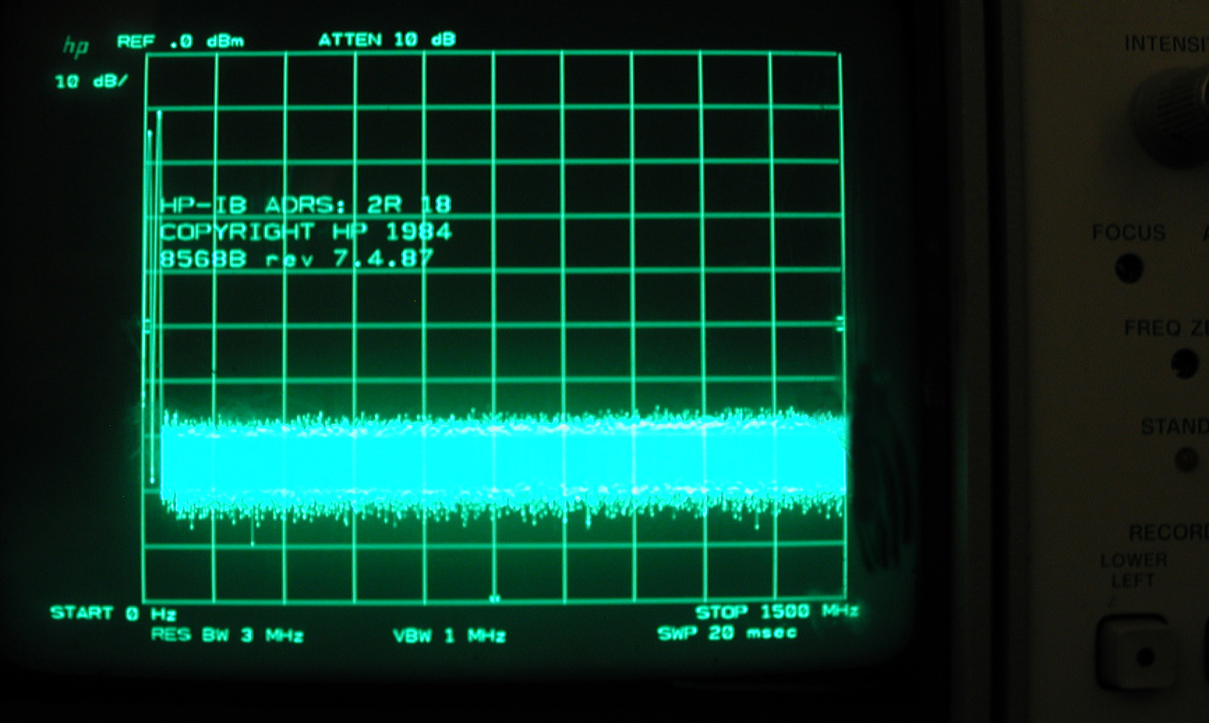
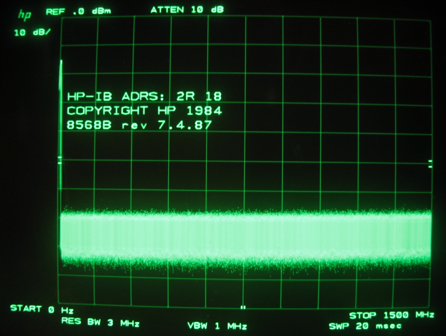
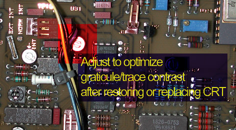
The display looked dramatically better after this initial treatment. The focus was perfect on all elements of the display, and the intensity was improved as well. But there was still a discrepancy in intensity between the text characters and the rest of the display. A subsequent pair of two three-second "zaps" at 70 mA had no visible effect. However, adjustment of the INT LIMIT and INT GAIN trimpots on the Z-axis board resolved the issue entirely; the optimum settings came at the maximum limit of INT LIMIT and the minimum limit of INT GAIN.
Prior to the restoration attempt, these trimmers had little or no effect. I don't believe the 70-mA pulses were necessary or helpful... but the fact that the CRT survived them makes me think that a 40-mA treatment is relatively safe for these tubes.
The second photo near the top of this page was taken at this juncture, immediately after the adjustment of the INT LIMIT
and INT GAIN trimmers.
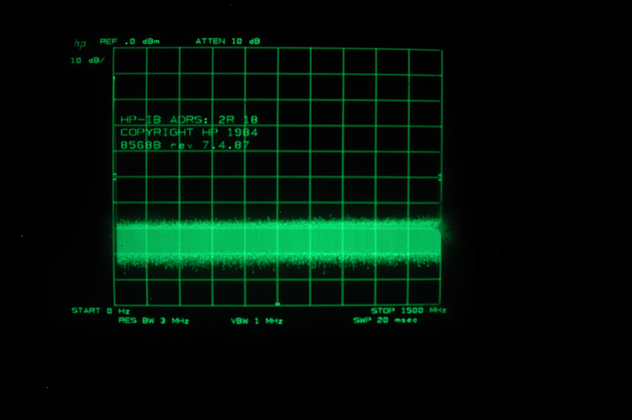
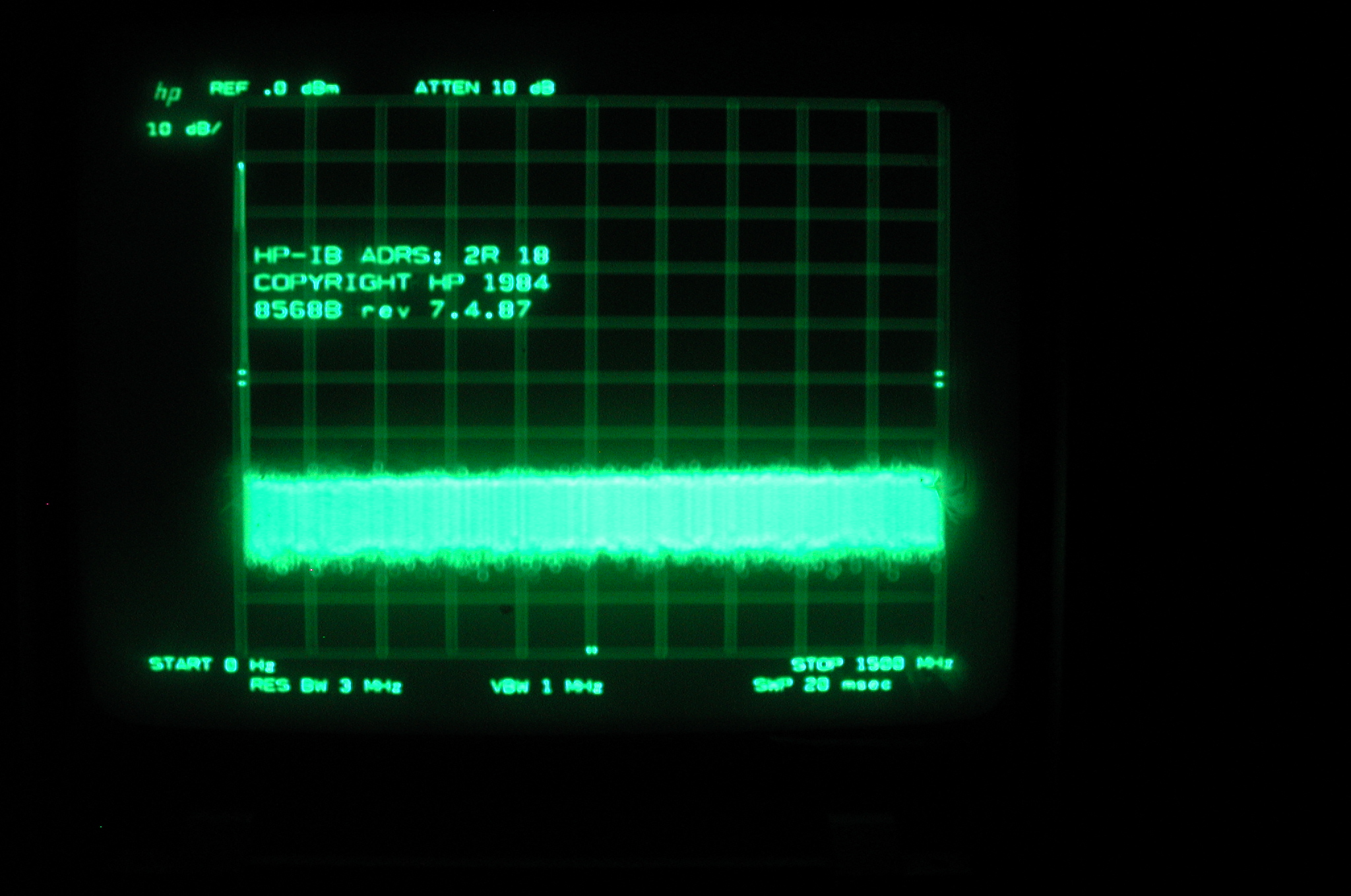
What isn't apparent in this simple "before and after" presentation is just how different the two photos really
are. When I took the first photo the CRT wasn't putting out much light at all, even at wide-open intensity. As a result, the
camera took a 2/3 second exposure... which is why the intensity control and panel fascia are so clearly visible in the "before" photo.
When I took the "after" photo, the CRT itself was putting out so much more light that
the camera was able to take the shot at 1/5 second. Everything else looks darker, but it wasn't -- the lighting conditions were
identical. The CRT is just that much brighter! For at least 100-200 hours after the restoration experiment, the CRT's
performance was basically that of a new tube.
After demonstrating that it's possible to restore a worn-out HP 85662A CRT to near-mint quality, the next question is obvious: "Sure, but for how long?" To get an answer, I moved the HP 8568B / 85662A system to a dark closet and placed a camera tripod in front of it. My plan was to leave the analyzer running for 1,000 hours, taking two photos per day at both centered (12:00) and maximum settings of the intensity control. This would allow me to observe and record any regression.
The good news is that during the first 300 hours of the long-term test, I observed little or no regression. The tube looked great, and seemed to be on track to stay that way. The bad news is that it took me a couple of weeks to understand all of the subtleties of my Nikon Coolpix's manual-operation mode. For various reasons, the first 300 hours of the test period, covering almost two weeks at the end of June 2006, did not yield photos that were comparable to those taken during the final 700 hours.
Consequently, the videos above cover the last 29 days of the test, or roughly 700 hours. They play at three frames per second, equivalent to 333 milliseconds per 24 hours of operating time. The first video contains frames taken with the intensity control at 12:00; the second with the control fully clockwise.
The executive summary is that visible regression does progress fairly rapidly in the video series. Things looked good for 500-700 hours, but by the end of the 1,000-hour run, the tube was only marginally usable. Interestingly, neither focus nor intensity degradation was monotonic over time. Like Charlie Gordon's character in Flowers for Algernon, the CRT enjoyed a temporary reprieve, followed by a slow, sad decline marked by good days and bad days.
So was the experiment a success, or a failure? That depends, as always, on your application. When you see an instrument whose CRT is as worn-out as this one was, you can assume that it happened because the instrument was left on all day, every day, over a period of several years... possibly in a round-the-clock factory or broadcast-studio setting. It's not worth trying to restore a CRT if your efforts are only going to buy another 3-4 weeks of service life in a 24/7 environment.
But if you're a ham operator or other hobbyist, or even a professional engineer with a home lab full of surplus equipment, 500-1000 hours is a long time.... at least a full year of productive Saturdays!
Some additional factors to consider:
- Operation at higher filament voltage. When I first received this display unit, I ran it for a few hours with an
extra turn on the high-voltage transformer's filament winding (see photo at right). That's a standard trick to extract some
additional operating time out of a weak CRT; I've used it to good effect on Tektronix tubes that aren't prone to focus
degradation. It did boost the intensity in this case, but the focus problems remained. (It's also worth noting that some
of the brightness improvement remained after I removed the extra turn. That's the only reason you can even see the text
in the "before" photo at the top of the page!)
I didn't reinstall the extra filament turn after the 1,000-hour test period; perhaps it would have helped.
- Remember that this tube wasn't a run-of-the-mill "soft CRT" when I received it... it was essentially dead. It's
reasonable to think that most restored tubes will last longer.
- The process needs refinement. There's no reason to think that three 40-mA ramps is the optimum treatment for any
given tube, including this one. It's possible that using a slowly-ramping Variac instead of a current-limited pulse generator is a really
bad idea. It's also possible that the unnecessary 70-mA shots were harmful to the newly-exposed "good" cathode surface.
Only through further experimentation on other tubes will it become possible to say what works and what doesn't. A single test case doesn't prove much.
- Multiple restorations may be possible, to a limited extent. The photos below are the last two still frames in the 1,000-hour test series...

... followed by two photos shot after an additional application of three 40-mA ramps from the Variac.
It appears that the secondary restoration compensated for the tube's last 200-300 hours of operating time, bringing it back
to the point where rapid regression was just getting under way. I'd expect even more-rapid regression this time around.
Errata and Updates
September 12, 2006 Sam Goldwasser's excellent TV and Monitor CRT FAQ also has a lot of great information and user contributions on CRT restoration. The larger Repair FAQ has been a Usenet mainstay for years, and it's good to see that it's still being updated.December 17, 2006 VE7EBR sends along an impressive pair of before/after photos. Exposure is 1 second at f2.7 in both cases, and both photos may be enlarged by clicking on them.
According to VE7EBR, this particular tube required a higher restoration voltage level than mine did:
I was a bit concerned because I had to crank (the VARIAC) up to 240 Vdc, while watching the current, before something interesting happened. It was steady at around 1.5 mA and then (@ 240), it shot up to 80 mA. I then ramped the VARIAC and the filament voltage to zero quickly. I tried again and this time, the I/V relationship was totally different: The current grew steadily from zero Vdc and it reached 40 mA at about 120 Vdc. I shut down everything and re-connected the 85662A. What a sight... Even I can't believe the difference between the two pictures.
 January 17, 2007 Thanks to Eric, W2ZT, a Tektronix 494P with a weak CRT was given the treatment last week.
There's no "before" photo in this case, because the trace and readout text were almost entirely invisible, and would not have shown up on a photograph taken in daylight. This particular tube was restored by running its heater at about 8 VDC and drawing about 90 mA of grid current for a few seconds.
Initial attempts at 50 and 70 mA yielded only modest improvements in brightness, but after the 90 mA application, the tube really came to life. Maximum achievable brightness is down a bit from what you'd expect from a factory-new CRT, but there is no double-peaking or other nonlinear behavior, and focus is uniformly excellent.
February 28, 2007 Unfortunately, a later update from Eric confirms that the restored tube lasted only a few dozen operating hours before growing dim again. It seems that this particular CRT was just too far gone to save.
April 3, 2007 Successful restoration of a moderately dim/fuzzy CRT in an HP 8753A vector network analyzer resulted in the bright, sharp display below.
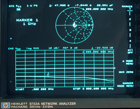
The display sections of the HP 8753A and 8753B network analyzers consist of an HP 1349A display module based on a proprietary green-phosphor CRT. Many older 8753A/B CRTs, including this one, are plagued with the same age-related focus degradation as the HP 85662A tubes. Quite a bit of usable life remained in this example, but defocusing at higher intensities was becoming pronounced, so it seemed like a good candidate for a restoration attempt.
The CRT socket connections used wire colors similar to those in the HP 85662A display, so it was easy to locate the control-grid (blue) and cathode (yellow) pins. The filament pins were located to either side of the index key on the tube base. However, the CRT's filament-voltage rating was not documented in HP's rather-limited service literature for the 8753A.
A multimeter with true-RMS capability and good high-frequency AC response can be used to measure CRT filament voltages directly. But because filament supplies are sometimes biased a few thousand volts beneath ground potential, precise measurement of low filament voltages requires you to use a battery-powered DMM, keeping its case and test leads well away from any grounded objects including your own appendages. "Floating" a meter in this fashion is extremely hazardous to both operator and equipment, and cannot be recommended under most circumstances. So I used a variable DC supply with an ammeter to try to guess what the CRT filament wanted to see.
The tube drew about 150 mA of filament current at 6.5VDC, but my initial restoration attempt showed that this was clearly not enough. As the grid current reached approximately 30 mA, it fell off abruptly and could not be increased beyond about 2 mA.
Filament voltage was then slowly increased to 12 VDC, with observed filament current in the 200-250 mA vicinity. This allowed the tube to draw the now-customary 70-90 mA of grid current during restoration. Two ramps to 90 mA were applied with the Variac, each lasting 1-2 seconds.
 Upon reinstallation of the monitor in the 8753A, the display remained blank. Either the initial attempt to draw grid current at a low
cathode temperature had damaged the remaining emission surface, or some other aspect of the restoration process
had reduced the tube's sensitivity, so I had to feel my way through the menus to turn up the intensity. This yielded a bright display...
but differential intensity between the trace and graticule elements was excessive. The graticule was barely visible, while
the trace and text were much too intense.
Upon reinstallation of the monitor in the 8753A, the display remained blank. Either the initial attempt to draw grid current at a low
cathode temperature had damaged the remaining emission surface, or some other aspect of the restoration process
had reduced the tube's sensitivity, so I had to feel my way through the menus to turn up the intensity. This yielded a bright display...
but differential intensity between the trace and graticule elements was excessive. The graticule was barely visible, while
the trace and text were much too intense.
Examination of the HP 1349A's CRT driver board revealed what appeared to be separate intensity-control trimmers for both fixed ("normal") and externally-controlled applications, along with a jumper to select them. Because the analyzer's main CPU controls the display intensity, the external intensity-control trimmer was the correct one to adjust in this case.
Both trimmers are visible in the photo at right, just beneath the 3-pin connector from the intensity-control DAC. Once the external intensity trimmer was located, it didn't take long to obtain a near-mint-quality display from the restored CRT.
Working with the DISPLAY->MORE->INTENSITY/FOCUS
menu options, I adjusted this trimmer
for nominal brightness at intensity level 25. The CENTER FOCUS control on the HV assembly was then adjusted for a sharp display
with a focus setting of 50. These settings were then "baked" as the analyzer's power-up defaults using the procedure in the
service manual (08753-90156, Adjustments and Correction Constants section, page 4.)
Feburary 15, 2008 According to the 1349A/D service manual (HP part number 01349-90901) from Artek Media, the CRT's specified filament voltage is 5.9V RMS. I don't know how safe it is to operate a CRT at 2x the rated filament voltage during restoration; obviously burnout becomes a real risk at some point. It seems prudent to use 9 VDC at first, advancing to 12 VDC only if the tube fails to draw enough grid current at the lower filament voltage. (Actually, 9.5 VDC may be a good compromise; see the update below from September 4, 2021.)
October 3, 2009 Martin, G6CGI, recounts some details of his successful CRT restoration in a Cushman CE-15 spectrum monitor.
There was no glimmer from the CRT at any setting of intensity or focus. Use of a scope detected signs of life at the deflection plates. I was able to short the pairs of plates together at the amplifier outputs. In a darkened room at maximum everything I could just see the faintest mark in the centre of the CRT. I used the bench DC supply to put 10V on the (6.3V) CRT heater, and applied my high voltage bench supply to the cathode and g1 after about one minute. This supply is variable from zero to 500V DC up to 100 mA. At around 50 volts PD current shot up from nothing to around 80mA with noticeable fluctauations. I ramped back the voltage to zero, and tried another 2 excursions to about 50 volts where the current settled to a smooth 70mA. Duration of these excursions was about 3 seconds each. I reconnected the CRT and found after adjusting the intensity and focus I had a very acceptable trace!Later (after I made up a high-resistance probe) I was able to measure the EHT in the voltage doubler and the divider chain. It was rather less than the values given in the circuit diagram. I suspect leaky caps in the divider and the divider chain and will replace these when I am able to locate some suitable ones.
October 25, 2011 Charles, WB3JOK/0 reports some good initial results with a standard TV-style CRT:
I had acquired a "Gunforce" arcade game (for $10!) with the standard RCA 19VLP22 color CRT that was extremely dim and poorly focused, which obviously had many hours on it. It was basically unplayable as-is so I figured I had nothing to lose after reading this page.In the meantime, some offline correspondence has indicated that connecting G1 and G2 together, when possible, can yield better results. At least some of the commercial restoration gear does this. The correspondent, who works for a CRT manufacturer, recommends a 1-minute warm up at normal heater voltage, followed by a 3-minute ramp to 1.8x normal heater voltage and a 1-minute soak at this level. Then, back the heater voltage down to a "slightly elevated" level and run for 20-35 minutes with 3-10 mA into the grids, with 80% of the total current going to G1 and 20% to G2. This strategy may provide more post-restoration operating life with less risk of cathode damage (although I've yet to hear of any actual damage caused by the short high-current ramps described above.)After looking up the tube pinout, I applied 7.5 vdc to the (nominally 6.3v) heaters. I connected my Heathkit 0-400 vdc, 100 ma power supply (through a 5k current limiting resistor) to each of the cathodes, with the positive terminal to G1. Each one initially had no visible beam current on the 0-100 ma meter (1 division = 5 ma) at 350v. But after about 10-15 seconds or so with steady 350v applied, the needle twitched and suddenly shot up to 70 ma, at which point I quickly removed the HV. The beam current would then ramp up linearly to at least 50 ma with the HV knob, but I did this test very quickly and briefly for fear of ruining the freshly rejuvenated surfaces.
A quick adjustment of brightness (which needed to be set considerably downwards) and refocus, and the picture is bright and sharp!
November 29, 2014 Here's something to consider before messing around with high voltage and fragile CRTs: LCD replacements have gotten really good in the eight years since I originally posted my experience with the 8568B CRT. Once you've used an 8568 or 8566 with an LED-backlit 1024x768 LCD, you will lose all interest in rejuvenating the CRT or otherwise spending five more minutes looking at it.
 SimmConn Labs offers just such an XGA LCD replacement, seen at left. And yes, it's that good. I used a 640x480 LCD from Test Equipment Plus for a few years before upgrading to SimmConn's, and while the TEP product is a worthwhile upgrade, you could argue that the original HP 85662A CRT is still superior because the 8566/8568 analyzers use 1001-point traces. Not so with SimmConn's XGA display. It's better than the original CRT, and sells for less than the TEP LCD.
SimmConn also offers replacements for the HP 8753A/B and related VNAs, as well as various Tektronix benchtop DSOs and various other instruments. My experience is limited to their 8566/8568 display upgrades, but I'd be surprised if the others aren't of similar quality.
(No affiliation with SimmConn, just a satisfied customer.)
September 4, 2021 Dick, W1QG has uncovered an interesting document describing a factory-sanctioned rejuvenation workflow for the 5083-6350 CRT, which was used in the 1349A display for the 8753A/B VNA and other instruments: Rejuvenation Process for CRT Part Number 5083-6350. Detailed pinout and factory test information for the tube is also included.
By the memo's 1997 date of publication, the 8753A/B models had given way to newer instruments with color CRTs and LCDs, and HP was no longer able to provide replacement monochrome CRTs for 1349A-based models at all. It's not clear whether the rejuvenation procedure was driven by contractual service commitments or simply by HP's late, lamented tradition of supporting their customers' investments for as long as possible. Regardless, it's a worthwhile read for anyone faced with a dim or fuzzy 1349A display.
As described above in the April 2007 entry, my own approach was very different, in that I forced the tube to draw grid current for a few seconds rather than relying on normal post-acceleration potential to get the job done over a 21-hour run. Note that the HP document calls for the CRT to be connected to its ET-5153-804 factory test station, which apparently generates a raster to avoid burning a dot into the center of the tube. If you choose to follow HP's restoration procedure, you'll need to make similar arrangements to sweep the beam.