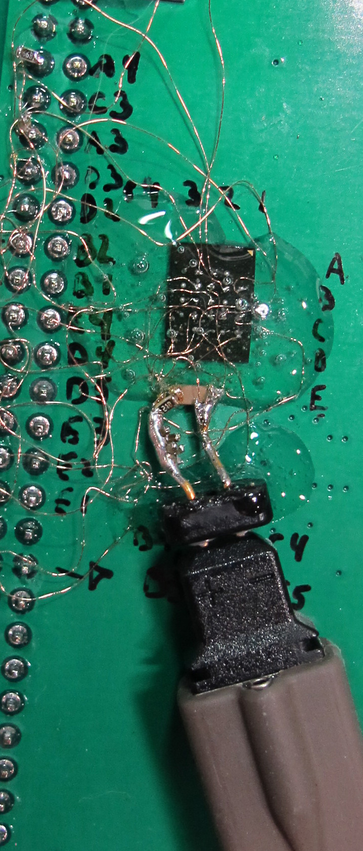
In this short take from the "Stuff the Data Sheet Said Not to Do" department, a Cypress S27KS0641 self-refreshing DRAM IC has been mounted dead bug-style to a carrier PCB for the ZTex 2.13A FPGA board. The BGA package was connected to the FPGA board's 0.100" headers with hand-soldered 40 AWG enamelled wires and subsequently covered with epoxy. No attention whatever was paid to crosstalk, EMI, trace impedance and length matching, or any other topics in the HyperRAM layout guide. FCC officials were not contacted for comment.
The goal of the experiment was to build intuition for the behavior of a typical 1.8V CMOS logic IC with various supply bypass capacitance values. Waveform data was captured with a Tektronix P6248 1.7 GHz differential probe across the bypass capacitor under test. Ceramic capacitors of 0402 size were tested in values of 10 pF, 100 pF, 10 nF, 100 nF, and 1 uF. (The 1206 capacitor visible in the photo at right was removed from the circuit.)
To make the test even more "interesting," this particular part performs DDR transfers with single-ended pins. Among other frequencies generated and used by the FPGA and its associated USB chip, there is significant energy at 78 MHz, 48 MHz, and the doubled clock frequency of 96 MHz, along with its higher-order harmonics.
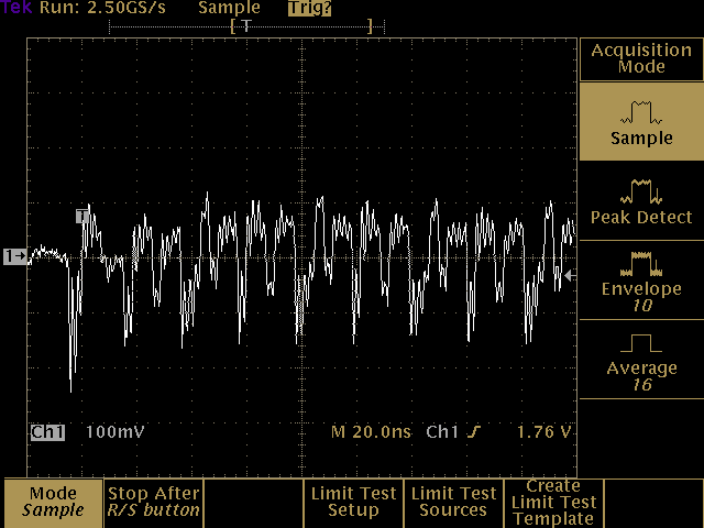
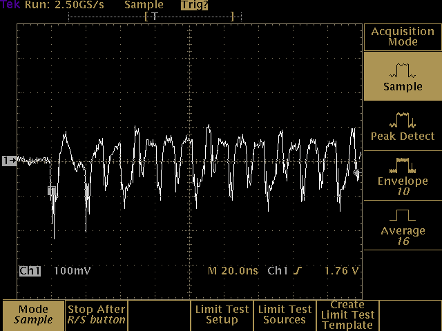
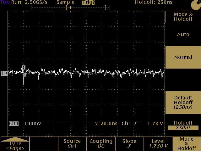
The screenshots below were taken during a typical register-read operation. The test ran successfully with all combinations of bypass capacitance -- and none at all -- in place.

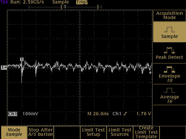
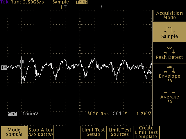
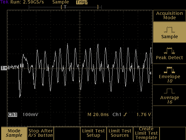
The use of separate bypass capacitors with values in the pF range is unnecessary in the absence of specific reasons to the contrary. They should never be used by themselves at the point of load. When multiple bypass capacitors are used in a single stage, there's a good argument in favor of choosing the same value for all of them.